64
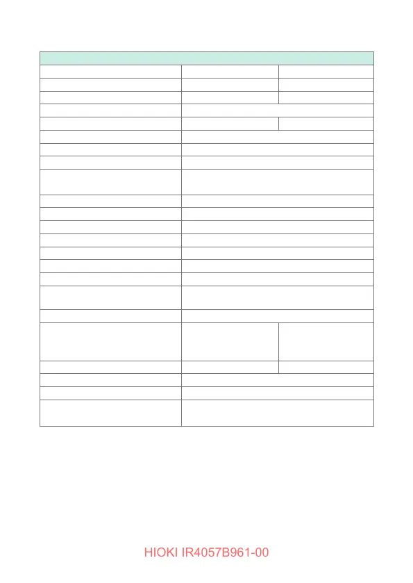
Basic and Accuracy Specications
PV
Ω
Measurement (IR4053 and IR4055 only)
Measurement voltage (DC)
PV
Ω
500 V PV
Ω
1000 V
Maximum displayed value
2000 M
Ω
4000 M
Ω
1st effective measuring range [M
Ω
]
0.200 to 500 0.200 to 1000
Accuracy (Tolerance)
±4% rdg
2nd effective easuring range [M
Ω
]
501 to 2000 1010 to 4000
Accuracy (Ttolerance)
±8% rdg
Other measuring range [M
Ω
]
0 to 0.199
Accuracy (Tolerance)
±2% rdg ±6 dgt
Effect of temperature (E
3
) Accuracy × 1.0 (applicable to the operating
temperature range other than 18°C to 28°C)
Effect of humidity
Accuracy × 1.0 and within allowance
Effect of magnetic eld
Accuracy × 0.5
Impact of positioning (E
1
)
Not applicable
Effect of supply voltage (E
2
)
Accuracy × 1.0 and within allowance
Effect of superimposing DC voltage
Within ±10%
Possible number of measurements
1000 times or more
Overload protection
660 V AC (10 s), 1200 V DC (10 s)
Display update interval
(no update during response)
Within 1.0 s
Open voltage*
1 to 1.2 times of rated measurement voltage
Lower limit resistance value to
maintain rated measurement
voltage
20 M
Ω
±5% 20 M
Ω
±5%
Rated current
0.025 mA ±20% 0.05 mA ±20%
Short-circuit current
1.2 mA or less
Response time
Within 4.0 s (Measurement start → Display)
Range conguration
See explanation for 500 V and 1000 V of
the insulation resistance measurement
* For the PV
Ω
measurement function, the output voltage is divided by the
1 M
Ω
resistor and the resistor connected between measurement terminals
because a 1 M
Ω
current limiting resistor is connected to the EARTH terminal.
Example: If a DMM with input impedance 10 M
Ω
is used to measure an open
voltage, the voltage is divided by 1 M
Ω
and 10 M
Ω
.
 Loading...