Screen Organization and Operational Overview
2
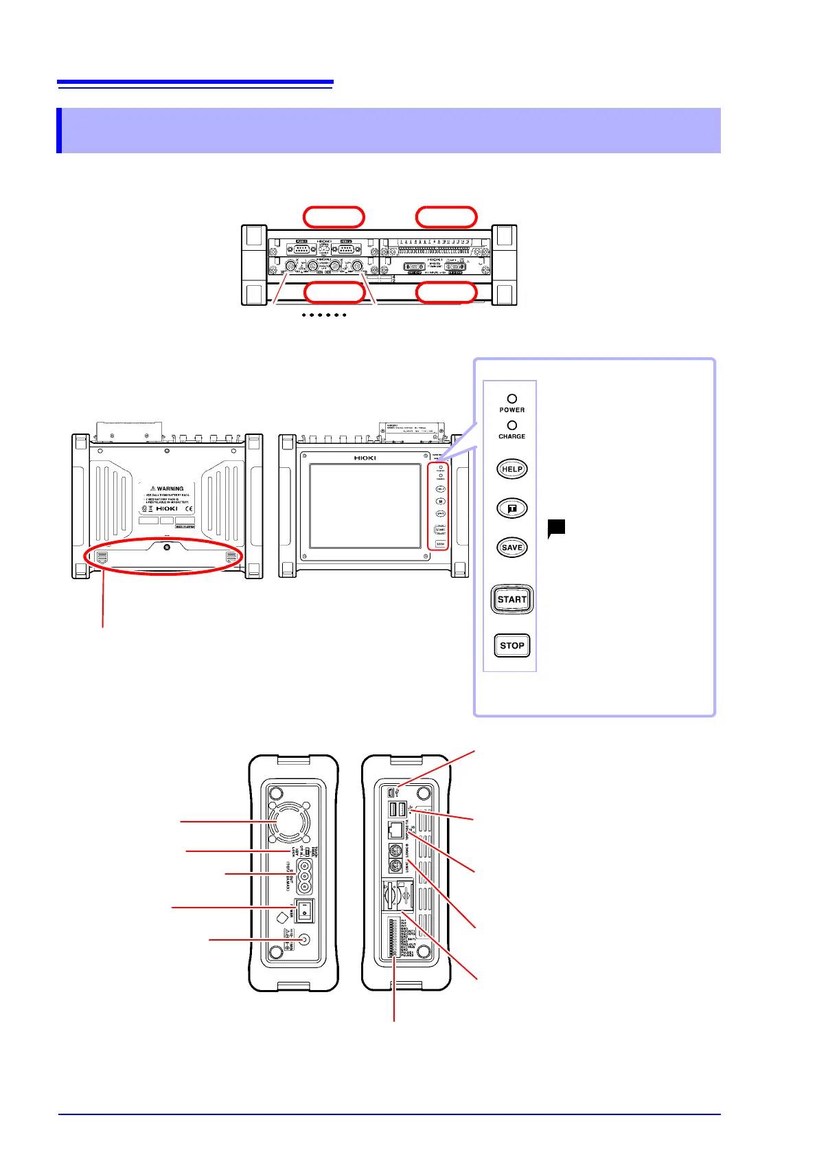
Part names
Screen Organization and Operational Overview
Analog input terminals
(BNC terminals)
Connect optional connection
cords, clamps, and other input
sources here.
Battery compartment cover
Install the Z1003 Battery Pack here.
Ventilation holes
(Do not block.)
POWER (LED)
Turns green when the power is on.
CHARGE (LED)
Turns orange when the instru-
ment is charging.
HELP key
Displays an explanation of the
screen display.
(forced trigger) key
Applies a user-specified trigger.
SAVE key
Saves data manually.
START key
Starts measurement. The key
turns green while measure-
ment is in progress.
STOP key
Stops measurement.
USB cable slot
Connect the included USB cable when con-
necting the instrument to a PC.
USB flash drive slot
Connect a USB flash drive here.
100BASE-TX connector
Connect a LAN cable here.
LOGIC terminals
Connect optional logic probes.
SD memory card slot
Insert an SD memory card.
Input modules
(up to 4 can be installed)
UNIT 2
UNIT 4UNIT 3
Back
Front
Top
Left side
Right side
CH1-1 CH1-4
UNIT 1
AC adapter socket
POWER switch
External power supply
terminals
External control terminals
KEYLOCK switch