Ring/Network coupling
Redundanz L2P
Release
5.0
04/09
5.2
Preparing a Ring/Network coupling
77
Note: Configure the coupling port and the redundancy ring ports on different
ports.
Note: If VLANS are configured, note the VLAN configuration of the
coupling and partner coupling ports.
In the Network/Ring Coupling configuration, select for the coupling and
partner coupling ports
– VLAN ID 1 and “Ingress Filtering” disabled in the port table and
– VLAN membership U in the static VLAN table.
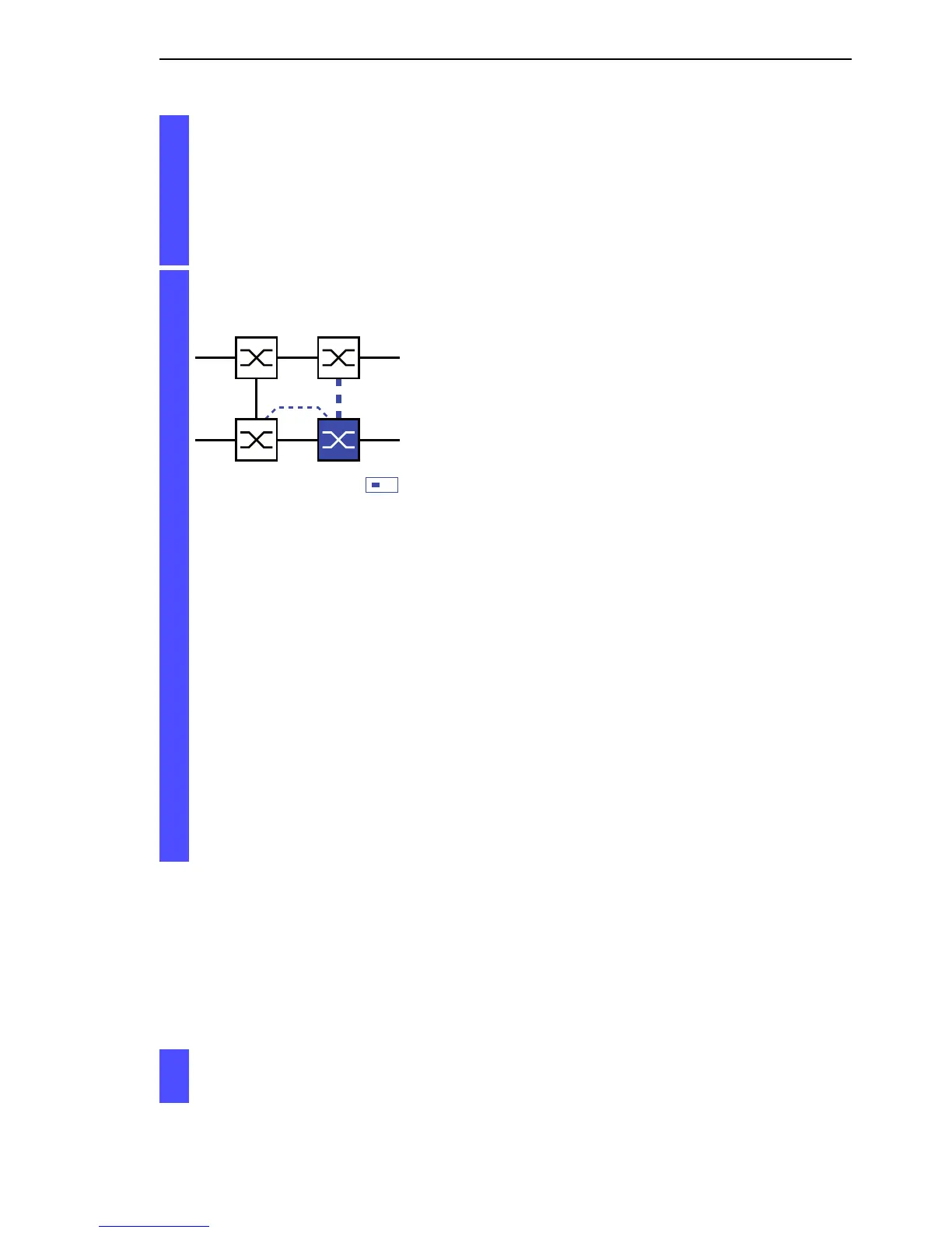
Select two-Switch redundant coupling
with control line (see fig. 39).
Figure 39: Two-Switch coupling with control line
1: Coupling port
2: Partner coupling port
3: Control line
The following settings apply to the Switch displayed in blue in the
selected graphic.
Select the coupling port (see fig. 38), (see table 11).
With “Coupling port” you specify at which port you are connecting
the network segments.
If the STANDBY DIP switch is ON, connect the main line to the
coupling port.
Select the control port (see fig. 38), (see table 11).
With “Control port” you specify at which port you are connecting the
control line.
Activate the function in the “Operation” frame (see fig. 31).
You now connect the redundant line and the control line.
IO
STAND-BY
12
3