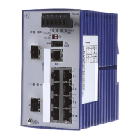
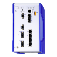
26
RS20/RS30...U
Release
01
06/2012
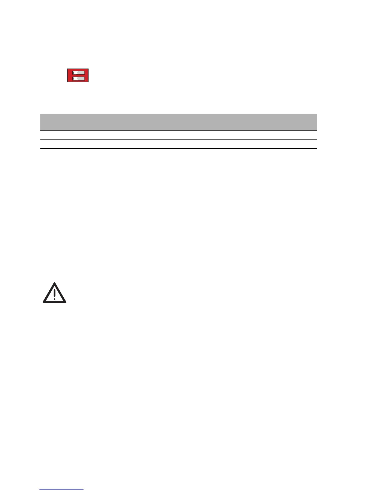
2.1.3 Adjust DIP switch settings
The 2-pin DIP switch on the front panel of the device gives you the following
options:
Figure 10: 2-pin DIP switch
Note: DIP switch “SW2” is not being used, so the switch setting has no effect.
State on delivery: both DIP switches “OFF”.
No ports have been learned, and link monitoring is disabled at the ports.
Before starting operation of the device, check whether the default settings
of the DIP switch correspond to your requirements.
2.1.4 Connecting the terminal blocks for supply voltage
and signal contact
The supply voltage and the signal contact are connected via a 6-pin terminal
block with a snap lock.
Caution!
Note the safety instructions (see page 5 “Safety instructions”) and
only connect a supply voltage that corresponds to the type plate of
your device. Make sure that the contact load capability of the signal
contact is not exceeded (see page 34 “General technical data”).
Supply voltage
Redundant power supplies can be used. Both inputs are uncoupled.
There is no distributed load. With redundant supply, the power supply unit
supplies the device only with the higher output voltage. The supply
voltage is electrically isolated from the housing.
You can choose between DC or AC voltage when connecting the supply
voltage. You use the +24V and 0V pins to connect the AC voltage (see
fig. 11).
LA learn switch
Item
Learn ports Link monitoring
ON on on
OFF off off