RS20/RS30...U
Release
01
06/2012
27
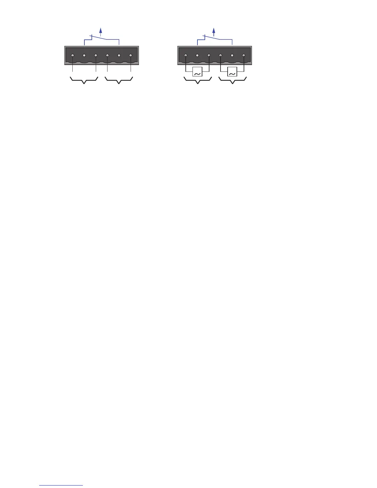
Figure 11: Connecting the supply voltage at the 6-pin terminal block
1 – DC voltage, voltage range: 9.6 V DC to 60 V DC
2 – AC voltage, voltage range: 18 V AC to 30 V AC
Note: With non-redundant supply of the main voltage, the device reports
a loss of power. You can avert this message by supplying the voltage over
the two inputs.
“FAULT” signal contact
The signal contact (“FAULT”, for pin assignment of terminal block, see
fig. 11) monitors the functioning of the device, thus enabling remote
diagnostics.
A break in contact is used to report the following conditions via the
potential-free signal contact (relay contact, closed circuit):
The detected inoperability of at least one of the two voltage supplies
(voltage supply 1 or 2 is below the threshold value).
The device is not operational.
The defective link status of at least one port with active link monitoring.
In the delivery state, link status monitoring is deactivated.
The loss of ring redundancy reserve.
A detected error during the self-test.
Pull the terminal block off the device and connect the power supply
and signal lines.
2.1.5 Installing the device on the DIN rail, grounding
Mounting on the DIN rail
Mount the device on a 35 mm DIN rail in accordance with DIN EN
60175.
Attach the upper snap-in guide of the device into the DIN rail and press
it down against the DIN rail until it snaps into place.
Note: The shield ground wire of the twisted pair lines is connected to the
front panel as a conductor.