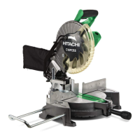
Fig. 32 Fig. 33
Cutting method of crown molding without tilting the saw blade
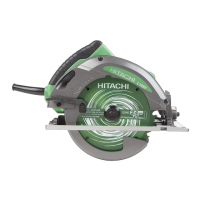
(1) Crown molding Stopper (L) and (R) (optional accessories) allow
easier cuts of crown molding without tilting the saw blade.
Install them in the base both-sides side to be shown in Fig. 34-
a. After inserting Tighten the 6mm knob bolts to secure the
crown molding Stoppers.
[Optional accessories used]
• Crown molding Vise Ass’y (Include Crown molding Stopper
(L))
• Crown molding Stopper (L)
• Crown molding Stopper (R)
Crown Molding
Vise Ass’y
(Optional
accessories)
6mm Wing
Bolt
6mm Wing
Bolt
Crown Molding Stopper (L)
(Optional accessories)
Crown Molding
Stopper (R)
(Optional
accessories)
6mm Wing
Bolt
Fig. 34-a
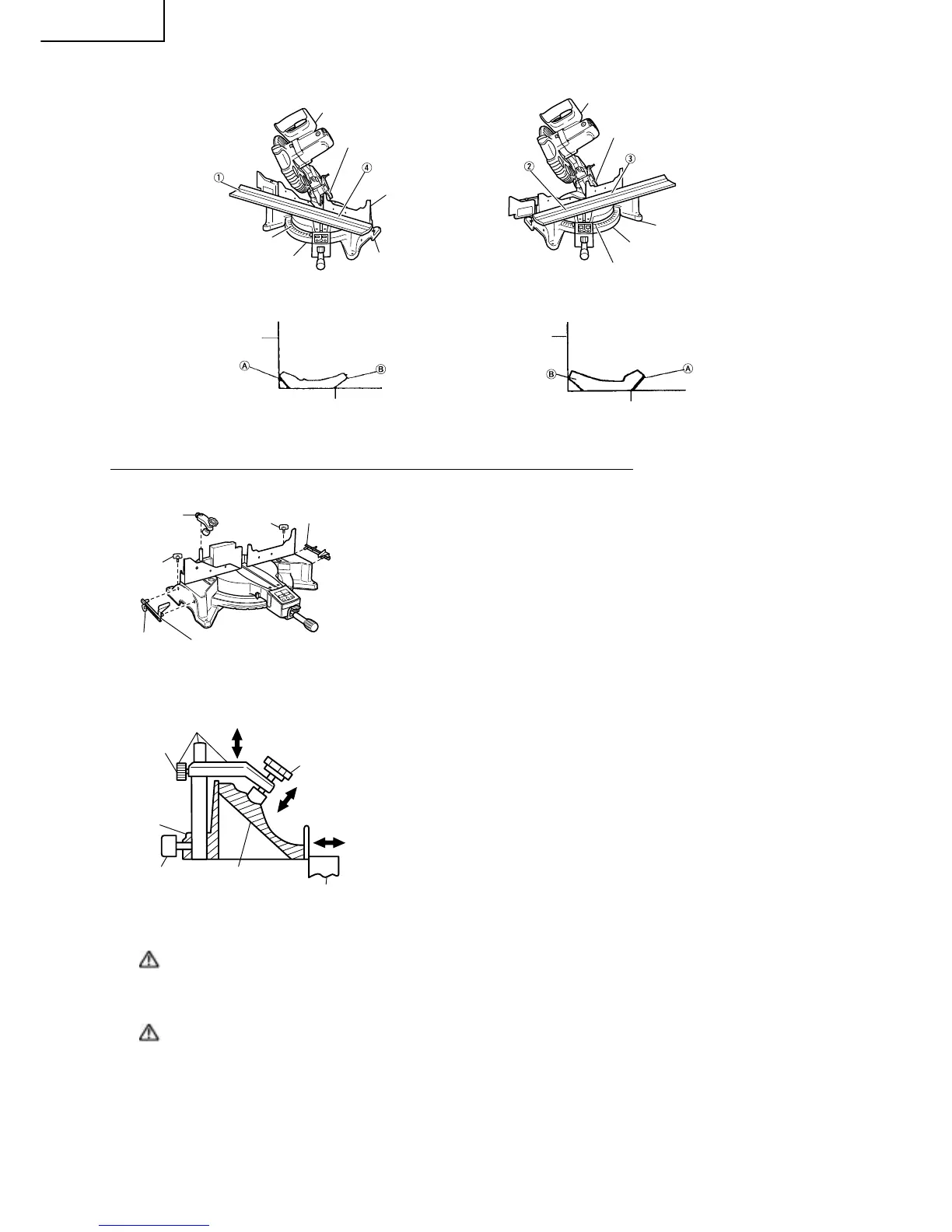
(2) The crown molding vise (B) (Optional accessory) can be
mounted on either the left fence (Fence (B)) or the right fence
(Fence (A)). It can unite with the slope of the crown molding
and vice can be pressed down.
Then turn the upper knob, as necessary, to securely attach the
crown molding in position. To raise or lower the vise assembly,
first loosen the 6mm knob bolt.
After adjusting the height, firmly tighten the 6mm wing bolt;
then turn the upper knob, as necessary, to securely attach the
crown molding in position. (See Fig. 34-b)
Crown Molding Stopper (L)
Crown Molding Stopper (R)
(Optional accessories)
Crown Molding
6mm Wing Bolt
Fence
Knob
6mm Knob Bolt
Crown Molding Vise Ass’y
(Optional accessories)
Fig. 34-b
WARNING: Always firmly clamp or vise to secure the crown molding to the fence; otherwise the
crown molding might be thrust from the table and cause bodily harm.
Do not bevel cutting. The main body or saw blade may contact the sub fence, resulting
in an injury.
CAUTION: Always confirm that the motor head (see Fig. 1) does not contact the crown molding
vise ass’y when it is lowered for cutting. If there is any danger that it may do so,
loosen the 6mm knob bolt and move the crown molding vise ass’y to a position
where it will not contact the saw blade.
Position crown molding with its WALL CONTACT EDGE against the guide fence and its CEILING CONTACT
EDGE against the crown molding Stoppers as shown in Fig. 34-b.
Adjust the crown molding Stoppers according to the size of the crown molding.
Tighten the 6mm wing bolt to secure the crown molding Stoppers.