45
CP-X2511N(C15I-25N2) / CP-X3011N(C15I-30N2) / CP-X4011N(C15I-40N2) / CP-X2011N(C15-20N2) / ED-X45N(C15-20N2)
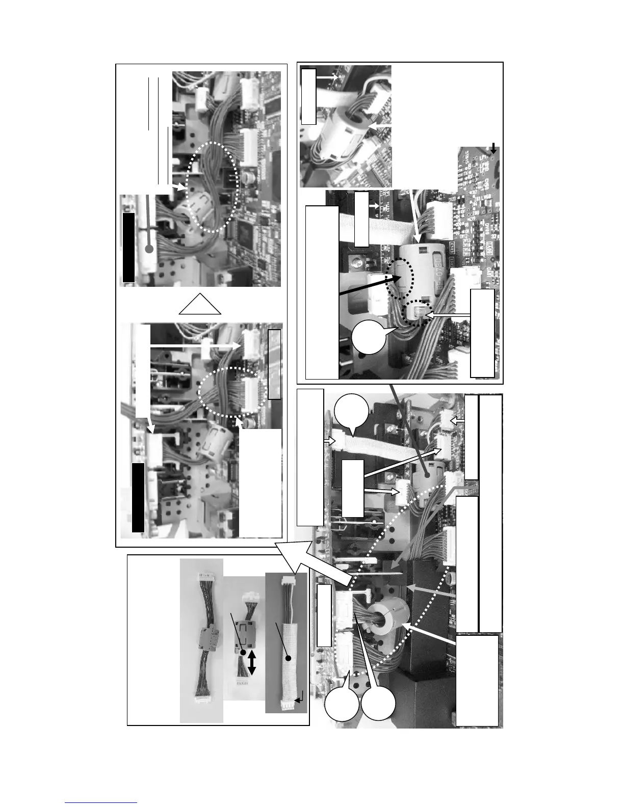
Wiring diagram 7
Wiring of MAIN board, INPUT board and RGB board
(1) Connect CNAUD, CNVID, CNRGB and CNUAR
(2) Attach shading sheet
Confirm that the ferrite cores and the tape are
attached in place properly.
Confirm that the claws of ferrite cores are
closed firmly and that any wires are not
pinched into the ferrite cores
Shading
sheet
INPUT board
INPUT board
MAIN board
INPUT board
①Connect the CNVID.
② Connect the CNAUD to
the MAIN board. Pass the
CNAUD between the CNVID
and the I/O panel.
③Turn the CNAUD around the
CNVID and connect to the
INPUT board.
Wrong wiring
may cause the shading
sheet dropped.
15 to 25mm
CNRGB
Cable tie
CNVID
CNUAR
Tape
No wires are not seen here.
Place the ferrite core
FE20 between the
input board and the
shading sheet.
CNAUD
CNVID
CNBAR
Hock the claw of the shading sheet to the metallic part of the
component video terminal block when attaching the shading sheet.
Connect the CNUAR.
Connect the end of CNUAR covered
with the tape to the IMPUT board.
Connect the
CNRGB.
BATTERY
board
RGB board
NG
RGB board
Put the ferrite core of the
CNRGB into the space between
the MAIN board and the RGB
board. Otherwise, it may
prevent from attaching MAIN
board block to the projector.
Place the claw of the ferrite core on the RGB
board side. Otherwise, this claw may damage
the electric parts of the MAIN board.
MAIN board
OK
CNRGB
Place the cable tie to
the RGB board side.
Pass the CNAUD and the CNVID
through the slit of the shading sheet.