Number Description
1
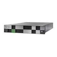
LEDs. From left to right, the LEDs are:
•
BMC Heartbeat
• LAN card 2
• LAN card 1
• Hard drive
• System standby power
2
Reset button.
3
Power button. Applies power to or removes
power from the SVP.
SVP rear panel
The only ports used on the rear panel of the SVP are the power sock
et and
the four LAN ports.
Number Description
1
Power socket. Attach the power cable supplied
with the SVP
.
2
Four LAN ports arranged as follows:
LAN3 LAN4
LAN1 LAN2
These ports connect to your IP network, the
management console PC, and the user LAN port
on each storage system controller.
Note: After the Initial Startup Wizard is run, the SVP can be used in non-
bridge mode. In this mode, the cables can be remo
ved from SVP ports LAN3
and LAN4 and attached to switches. For more information, contact customer
support.
48 Hardware description
Hitachi Virtual Storage Platform G400, G600 Hardware Reference Guide