List of figures
46Figure 52. Limits of temperature and humidity ........................................
45Figure 51. Temperature and humidity ...............................................
44Figure 50. Jumper settings for Disabling Auto Spin ...................................
43Figure 49. Jumper positions for capacity clip to 2GB/32GB ............................
42Figure 48. Jumper positions for 15 logical head default ...............................
41Figure 47. Jumper positions for normal use ..........................................
40Figure 46. Jumper pin assignment .................................................
39Figure 45. Jumper pin identification (2- and 3-disk model shown) .......................
39Figure 44. Jumper pin location (2- and 3-disk model shown) ...........................
38Figure 43. I/O address map .......................................................
37Figure 42. Ultra DMA cycle timings (Host Terminating Write) ...........................
37Figure 41. Ultra DMA cycle timing chart (Host Terminating Write) .......................
36Figure 40. Ultra DMA cycle timings (Device terminating Write) .........................
36Figure 39. Ultra DMA cycle timing chart (Device Terminating Write) .....................
35Figure 38. Ultra DMA cycle timings (Device Pausing Write) ............................
35Figure 37. Ultra DMA cycle timing chart (Device Pausing Write) ........................
34Figure 36. Ultra DMA cycle timings (Initiating Write) ..................................
34Figure 35. Ultra DMA cycle timing chart (Initiating Write) ..............................
33Figure 34. Ultra DMA cycle timings (Device Terminating Read) .........................
33Figure 33. Ultra DMA cycle timing chart (Device terminating Read) .....................
32Figure 32. Ultra DMA cycle timings (Host terminating Read) ...........................
32Figure 31. Ultra DMA cycle timing chart (Host terminating Read) .......................
31Figure 30. Ultra DMA cycle timings (Host pausing Read) ..............................
31Figure 29. Ultra DMA cycle timing chart (Host pausing Read) ..........................
30Figure 28. Ultra DMA cycle timings (Initiating Read) ..................................
30Figure 27. Ultra DMA cycle timing chart (Initiating Read) ..............................
29Figure 26. Multiword DMA cycle timings .............................................
29Figure 25. Multiword DMA cycle timing chart .........................................
27Figure 24. PIO cycle timings .......................................................
27Figure 23. PIO cycle timings chart ..................................................
26Figure 22. System reset timing .....................................................
26Figure 21. System reset timing chart ................................................
22Figure 20. Signal special definitions for Ultra DMA ....................................
22Figure 19. Table of signals ........................................................
21Figure 18. Power connector pin assignments ........................................
21Figure 17. Connector location (2- and 3-disk model shown) ............................
19Figure 16. PList physical format ....................................................
17Figure 15. Mode transition times ...................................................
16Figure 14. Random Access Performance ............................................
16Figure 13. Simple Sequential Access performance ...................................
15Figure 12. Data transfer speed .....................................................
14Figure 11. Drive ready time ........................................................
14Figure 10. Latency Time ..........................................................
14Figure 9. Single Track Seek Time ..................................................
14Figure 8. Cylinder switch time .....................................................
13Figure 7. Head switch time ........................................................
13Figure 6. Full stroke seek time .....................................................
12Figure 5. Mechanical positioning performance .......................................
12Figure 4. Command overhead ....................................................
11Figure 3. Cylinder allocation .......................................................
10Figure 2. Mechanical positioning performance .......................................
9Figure 1. Formatted capacity ........................................................
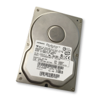
Deskstar 180GXP hard disk drive specifications
xi

 Loading...


