6.3.4 Jumper positions
6.3.4.1 16 logical head default (normal use)
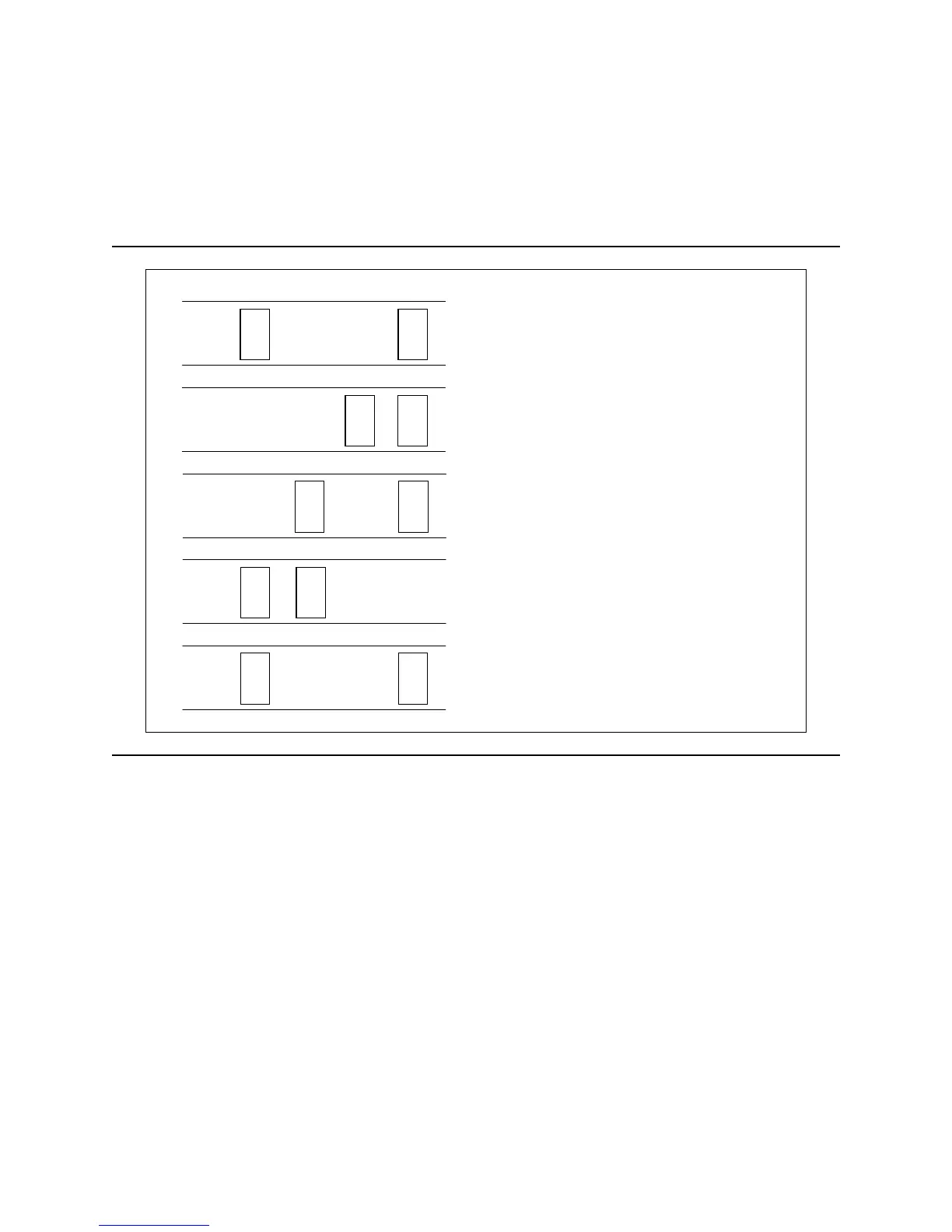
The figure below shows the jumper positions used to select Device 0, Device 1, Cable Selection, or
Device 1 (Slave) Present.
G
I
ECA
HFDB
DEVICE 0 (Master)
G
I
ECA
HFDB
DEVICE 1 (Slave)
G
I
ECA
HFDB
CABLE SEL
G
I
ECA
HFDB
DEVICE 1 (Slave) Present
G
I
ECA
HFDB
Shipping Default Condition
(DEVICE 0)
Figure 47. Jumper positions for normal use
Notes:
1. To enable the CSEL mode (Cable Selection mode) the jumper block must be installed at E-F. In the
CSEL mode the drive address is determined by AT interface signal #28 CSEL as follows:
y
When CSEL is grounded or at a low level, the drive address is 0 (Device 0).
y
When CSEL is open or at a high level, the drive address is 1 (Device 1).
2. In CSEL mode, installing or removing the jumper blocks at A-B or C-D position does not affect any
selection of Device or Cable Selection mode.
3. The shipping default position is the Device 0 position.
Deskstar 180GXP hard disk drive specifications
41
 Loading...