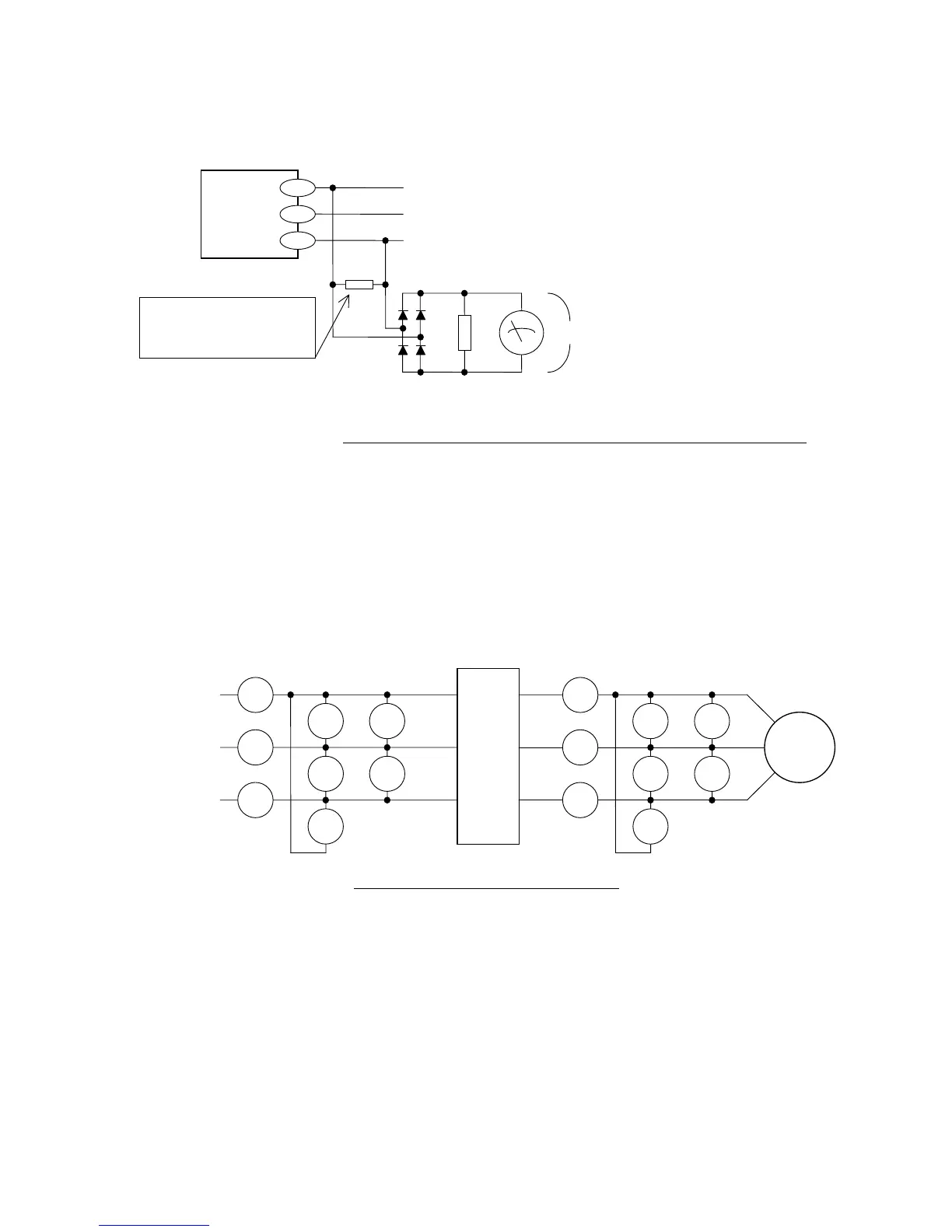
When there is no motor connected to the inverter, please use additional resistor like Fig. 7-2. There
will be a voltage at output terminal even the frequency command is naught due to the leakage current
of the semiconductor devices.
(2) Measurement of Input voltage and Input / output current
Use moving iron type ampere meter. (Refer to Fig. 7-3 and Table 7-1.)
(3) Measurement of Input and output power
Use electrodynamics type watt meter for single phase use. Make measurements for all 3 phases is
case there is an unbalance in voltages and currents.
Fig. 7-2. Output voltage measurement circuit (without motor)
U
V
W
Frequency
Inverter
2W
220kohm
Additional resistor
5kohm 30W (200V class)
100W (400V class)
+
V
DC
-
Fundamental wave
effective value : V
AC
= V
DC
* 1.1
Moving coil type DC Volt meter
300V (200V class)
600V (400V class)
Diode
600V 0.1A or above (200V class)
1000V 0.1A or above (400V class)
Fig. 7-3. Measurement Instruments
I
R
E
R
I
S
E
S
I
T
E
T
W
11
W
12
Frequency Inverter
L1
L2
L3 / N
I
U
E
U-V
I
V
E
V-W
I
W
E
U-W
W
O1
W
O2
Motor
L1
L2
L3 / N
U/T1
V/T2
W/T3
7-2

 Loading...