45
5. INSTALLING AND PIPING THE DSP [Piping the DSP Air Compressor]
・ This is to prevent the reciprocating compressor's air
pulsation from affecting this air compressor.
・ Typical operation is to run this air compressor as long
as possible as the primary and start, and stop the
reciprocating air compressor in parallel as a floating
trim air compressor, as required by the compressed air
demand.
①
Install the air receiver tank because this air
compressor is equipped with 2-step capacity control
system. To prevent the pressure fluctuation and to
maximize the energy saving feature, the minimum size
of the air receiver tank is indicated in the table blow.
5.4.5 Air Receiver Tank
② Install the air receiver tank of 620 USgal (2.26m
3
) of
more for the
AUTO operation, multi-unit control or
lead/lag operation in order to achieve the better energy
saving effect.
③ Install the air receiver tank of 620 USgal (2.26m
3
)of
more for using ECOMODE in order to achieve the
better energy saving effect on all load ratio.
Pressure detecting piping
Discharge
air
Stop valve
Flange
Motorized
isolation valve
Air receiver tank
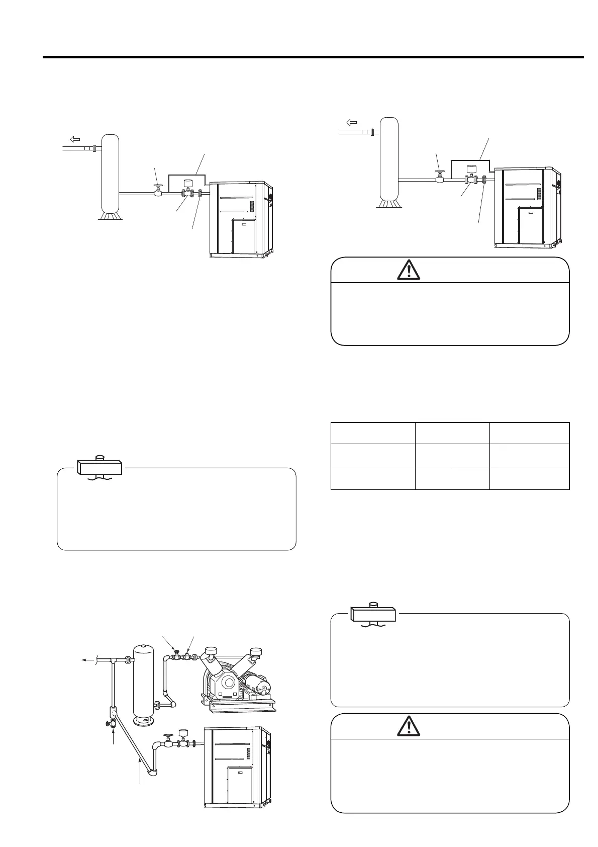
5.4.4 Reciprocating Compressor and
Parallel Piping
Check valveStop valve
Discharge air
Stop valve
Piping to air receiver
tank outlet
Model
Discharge pressure
psi (MPa)
Minimum capacity of
air receiver tank (m
3
)
DSP-45/55/75ATN
DSP-45/55/75WTN
100/125
(0.69/0.86)
620 USgal (2.26)
DSP-55/75VATN
DSP-55/75VWTN
100/125
(0.69/0.86)
400 USgal (1.24)
CAUTION
Do not install a check valve between this air
compressor and the air receiver tank. This
could result in short cycling (frequent loading
and unloading) and operating problems to the
capacity control system.
5.4.3 How to Install Automatic
Discharge Valve
The air compressor is equipped with AUTO restart/stop
function as a standard function. The pressure for
capacity control is detected at the secondary side of the
motorized isolation valve. Install the motorized isolation
valve and pressure detecting piping (standard accessory).
Connect the pressure detecting piping from upper side of
main piping to pressure detecting port of the air
compressor as above.
Install the pressure detecting piping as close as
motorized isolation valve. The operation with NOT
installed pressure detecting piping results in the relief
valve action.
Motorized
isolation
valve
Discharge
air
Stop valve
Flange
Pressure detecting piping
Air receiver tank
The motorized isolation valve is closed when the air
compressor is stops. The operation WITHOUT the
motorized isolation valve results in the backflow of
condensate from the plant compressed air system. Then
it results in the early damage of check valve, aftercooler
and etc by rusting
IMPORTANT
IMPORTANT
Failure to install an adequately sized air
receiver tank may cause the air compressor to
frequently load/unload. This may shorten the
mechanical life of the air compressor.
CAUTION

 Loading...