70
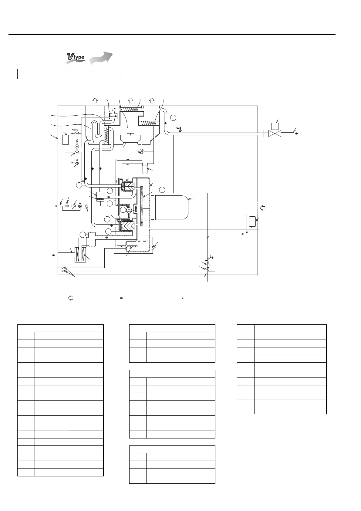
8. STANDARD COMPONENTS AND SUBSYSTEMS [Air/Oil/Water Flow]
Flow diagram
Air-Cooled
Legend of Sensors and Switches
Symbol
Part name
PS2
Pressure Sensor (discharge air pressure)
PS4
Pressure Sensor (oil pressure)
PS1
Pressure Sensor (interstage pressure)
TH2
Temperature Sensor (2nd-stage in)
TH4
Temperature Sensor (1st-stage out)
TH3
Temperature Sensor (2nd-stage out)
TH5 Temperature Sensor (oil)
THM
Temperature Sensor (for main
motor surface temperature)
63SV
Pressure Differential Sensor (For
suction filter clogging detection)
Capacity Control & Blowoff Air Flow
21 Air Intake Filter
22 Blowoff Solenoid Valve (1)
23 Blowoff Solenoid Valve (2)
24 Blowoff Silencer
Oil Flow
31 Oil Strainer
32 Oil Pump
33 Oil Relief Valve
34 Oil Cooler
35 Oil Filter
36 Temperature Control Valve
38 Oil Drain Valve
39 Oil Mist Remover
Air Flow and Other
51 Fan Motor
52 Enclosure
53 Air Intake Duct
54 Cooling fan
Legend of the Diagram
Compressor Air Flow
1 1st-Stage Airend
2 2nd-Stage Airend
3 Gear Case
4 Step-up Gear
5 Main Motor
6 Intercooler
7 Check Valve
8 Aftercooler
9 Air Relief Valve
10 Discharge Port
11 Check Valve
13 Orifice
14 Drain Solenoid
15 Y-type Strainer
16 Drain trap
17 Demister
18 Motorized isolation valve
19
Hi-Precooler (only for 125 psi (0.86 MPa type))
20
Drain separator
14
15
13
Air exhaust
Air exhaust Air exhaust
20
17
9
21
53
32
52
11
10
PS2
4
3
5
33
31
TH3
1
PS1
TH4
TH5
63SV
24
22
22
Air intake for
compressed air
38
39
13
35
14
PS4
15
2
Aftercooler condensate drain
Cooling air flow Compressed air flow Lubricating oil flow
18
THM
23
23
36
19
6
7
8
34
51
TH2
54
M
Oil drain
Oil drain
Control air for OMR
Air intake for
main motor
Compressed
air discharge
Intercooler
condensate
drain
Compressed Air Flow and Oil Flow

 Loading...