--- 28 ---
(b) Reassembly
Reassembly can be accomplished by following the disassembly procedures in reverse. However, special
attention should be given to the following items:
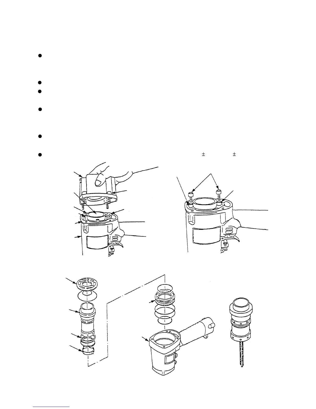
Be sure to check that the Cylinder [13] is provided with a 1-mm dia. hole (Fig. 15) before reassembly. Note
that mounting a wrong cylinder may cause a malfunction. There is no problem in facing the 1-mm dia. hole
in any direction when mounting.
Check that the free length of the Cylinder Spring [15] is about 42 mm.
Ensure that the convex surface side of the Piston [9] (illustrated in Fig. 14) is facing toward the Guide Plate
[25] side.
Reassembly of the Piston [9] can be most easily accomplished by inserting the Piston [9] into the Cylinder
[13] as illustrated in Fig. 13, and inserting the Piston [9] into the grooves on the Guide Plate [25] while
pulling the piston out in a downward direction.
When assembling Gasket (B) [4], ensure that its air vents are properly aligned with the air vents on the
Body Ass'y [19].
Tighten the four Hex. Socket Hd. Bolts M5 x 20 [1] to specified torque (85 5 kg
•
cm, 6.1 0.4 ft-lb).
Fig. 13
Cylinder Plate [12]
Body Ass'y [19]
Gasket (B) [4]
Cylinder [13]
Piston [9]
Hex. Socket Hd.
Botl M5 x 20 [1]
Exhaust Cover [3]
Air vent
Fig. 11
Cylinder Plate [12]
Cylinder Spring [15]
Cylinder Ring [14]
Cylinder [13]
Cylinder Guide [17]
Hex. Socket
Hd. Botl M5 x 20 [1]
Cylinder
Plate [12]
Threaded hole
for M5 bolts
Fig. 12
Body Ass'y [19]
Fig. 14


 To Next Page