31
PJ-TX100(C11H)
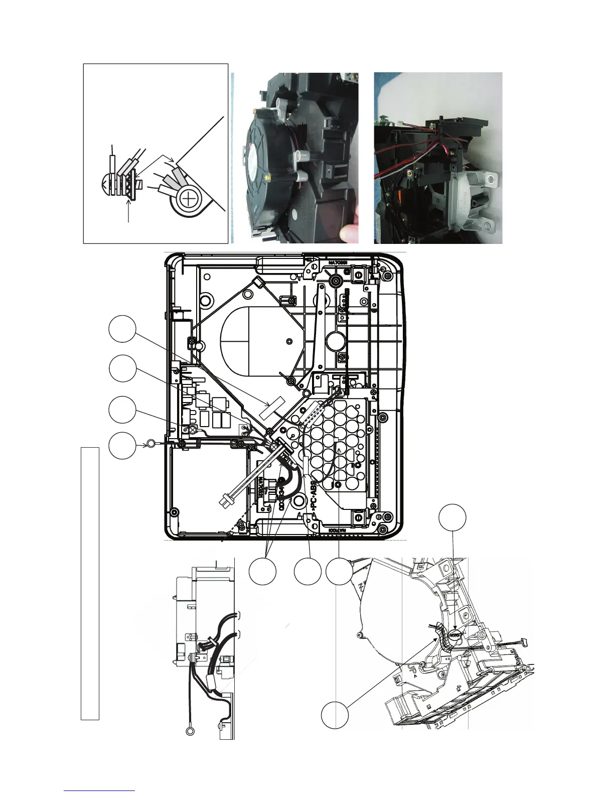
Wiring diagram 3 (C11H)
(1) Attach and wire CN1.
(2) Secure FG, CNSH, and CD2 to power block with screw.
Preparation of optical engine work and wiring for attachment of bottom case
CNBAR
CNPOW
TSW
CNSH
CN1
FG
CD2
Secure CNSH, FG, CD2, and crown washer to
power case with screw as shown below.
CNSH
CNSH
Power case
Crown
washer
FG
FG
CD2
CD2
Bend FG and CD2
ring lugs 45° as
shown.
Power case
Position ring lugs
so they do not
contact duct or
power case as
shown left.
Filter circuit board
Side of power case
(A side view)
A
To lamp door switch
FG
CD2
CNSH
Arrange FG, CD2, and CN1 wiring as
shown above.
Keep FEB1 close to filter circuit board.
ZTP2
Tape and secure panel fan
connector lead to curved
section of aluminum holder
with ZTP2.
Panel
fan
FEB1
Pass panel fan cable through positions shown
above.
Pass internal air temperature sensor cable through
positions shown above.
Leave away from this area for fitting
bottom case and lead wire.
 Loading...