3 Piping work and refrigerant charge
Refrigerant and drain hose installation
SMGB0099 rev.0 - 12/2016
120
3.5.8 RPI-(8.0/10.0)FSN3E-(f) - Ducted indoor unit
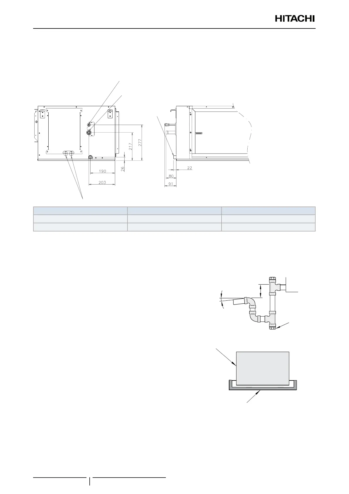
Refrigerant pipe installation
The location of the refrigerant pipe connections are shown below.
2
4
3
1 Liquid pipe
2 Gas pipe
3 Electrical connection
4 Drain pipe
Model Gas pipe mm (inches) Liquid pipe mm (inches)
RPI-8.0FSN3E(-f) Ø19.05 (3/4) Ø9.52 (3/8)
RPI-10.0FSN3E(-f) Ø22.2 (7/8) Ø9.52 (3/8)
? NOTE
When installing the pipes, leave enough space for maintenance work in the electrical box of the unit.
Drain pipe installation
For condense draining, prepare a polyvinyl chloride pipe with a
Ø25mm (outer diameter).
Fasten the eld supplied pipe to the drain hose with adhesive.
The drain piping should be performed with a down-slope pitch
of 1/25 to 1/100.
Connect a syphon, as shown at the gure below.
>75 mm
Slope 2%
Plug
? NOTE
• Keep Electrical Box and Drain Pipe connection free of refrigerant
pipes.
• If the relative humidity of the inlet air or the ambient air exceeds
80% in the place where the unit is installed, t an auxiliary drain
pan (eld-supplied) below the indoor unit, as indicated in the gure.
! CAUTION
It is very important the syphon installation in order to guarantee the
proper condensate draining.
Indoor unit
Auxiliary drain pan
(field-supplied)
Auxiliary drain pan
(eld-supplied)
Indoor unit
? NOTE
If there is excessive clearance between the drain pipe connection and the drain hose, add a sealing material between both parts in order
to t and not deform the drain hose.
 Loading...

