S1 series standard inverter
-219-
12.4.5 Insulation inspection
Check the motor and the insulation conditions of the motor cable before running the motor.
1. Ensure that the motor cable is connected to the motor, and then remove the motor cable from the
U, V, and W output terminals of the inverter.
2. Use a megameter of 500 V DC to measure the insulation resistance between each phase
conductor and the protection grounding conductor. For details about the insulation resistance of
the motor, see the description provided by the manufacturer.
Note: The insulation resistance is reduced if it is damp inside the motor. If it may be damp, you
need to dry the motor and then measure the insulation resistance again.
12.5 Breaker and electromagnetic contactor
You need to add a fuse to prevent overload.
You need to configure a manually manipulated molded case circuit breaker (MCCB) between the AC
power supply and inverter. The breaker must be locked in the open state to facilitate installation and
inspection. The capacity of the breaker needs to be 1.5 to 2 times the rated current of the inverter.
According to the working principle and structure of breakers, if the
manufacturer's regulation is not followed, hot ionized gases may escape
from the breaker enclosure when a short-circuit occurs. To ensure safe use,
exercise extra caution when installing and placing the breaker. Follow the
manufacturer's instructions.
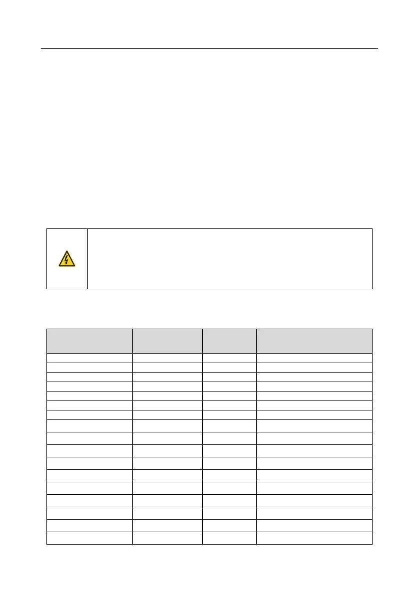
To ensure safety, you can configure an electromagnetic contactor on the input side to control the
switch-on and switch-off of the main circuit power, so that the input power supply of the inverter can
be effectively cut off when a system fault occurs.
Rated current of the
contactor (A)
 Loading...


