S1 series standard inverter
-35-
For models up to 2.2kW, it’s AI1(analog protentionmeter);
For modes >2.2kW, it’s digital potentionmeter;
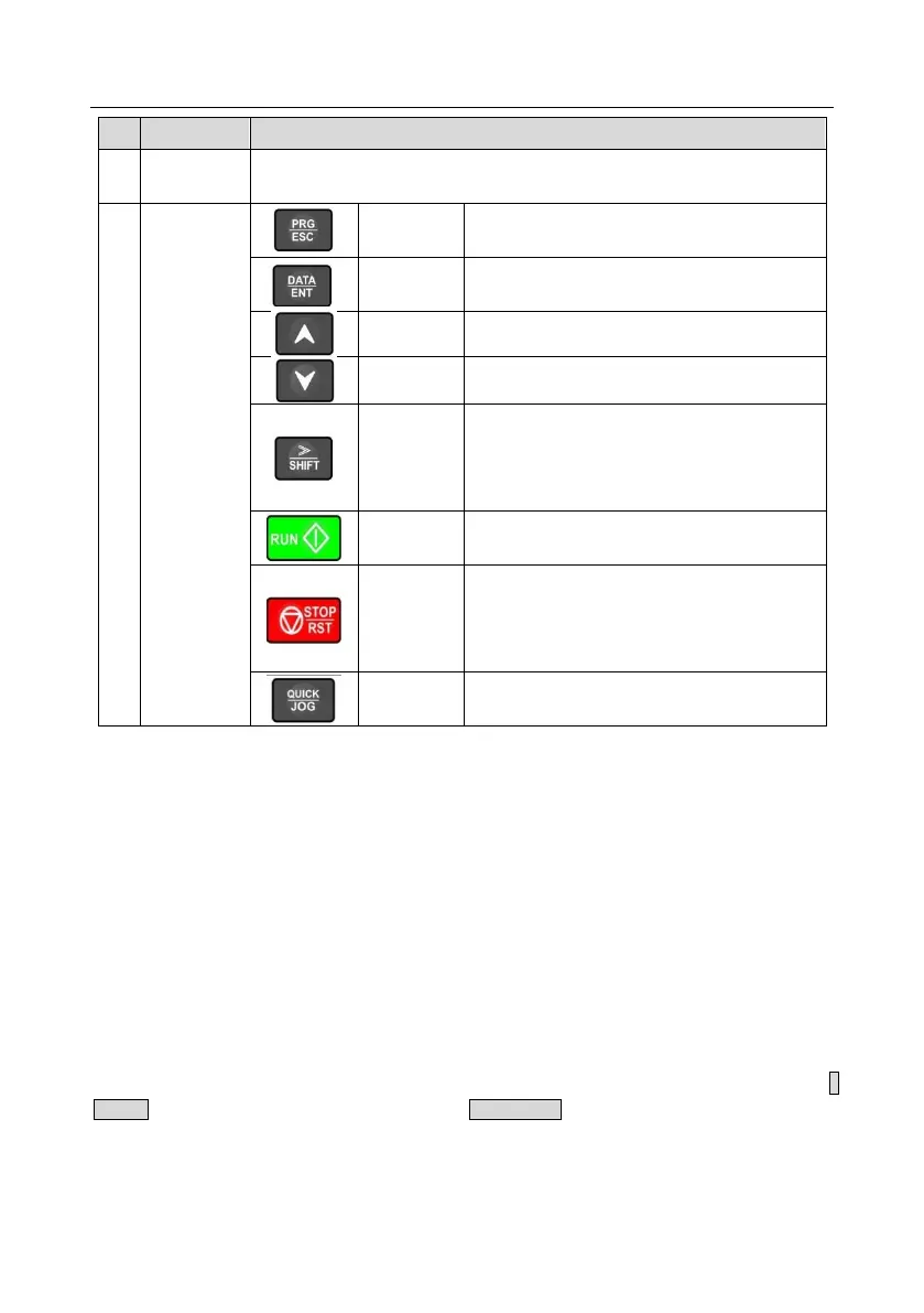
Enter or escape from the first level menu and
remove the parameter quickly
Enter the menu step-by-step
Confirm parameters
Increase data or function code progressively
Decrease data or function code progressively
Move right to select the displaying parameter
circularly in stopping and running mode.
Select the parameter modifying digit during the
parameter modification
This key is used to operate on the inverter in key
operation mode
This key is used to stop in running state and it is
limited by function code P07.04
This key is used to reset all control modes in the
fault alarm state
The function of this key is confirmed by function
code P07.02.
5.3 Keypad display
The display state of S1 series keypad is divided into stop parameter display state, running parameter
display stateand fault alarm display state.
5.3.1 Displayed state of stopping parameter
When the inverter is in the stopping state, the keypad will display stopping parameters which is shown
in figure 5.3.
In the stopping state, various kinds of parameters can be displayed. Select the parameters to be
displayed or not by P07.07. See the instructions of P07.07 for the detailed definition of each bit.
In the stopping state, there are 14 stopping parameters can be selected to be displayed or not. They
are: set frequency, bus voltage, input terminals state, output terminals state, PID given value, PID
feedback value, torque set value, AI1, AI2, AI3, HDI, PLC and the current stage of multi-step speeds,
pulse counting value, length value. P07.07 can select the parameter to be displayed or not by bit and》
/SHIFT can shift the parameters from left to right, QUICK/JOG(P07.02=2) can shift the parameters
from right to left.
5.3.2 Displayed state of running parameters
After the inverter receives valid running commands, the inverter will enter into the running state and
 Loading...


