S1 series standard inverter
-38-
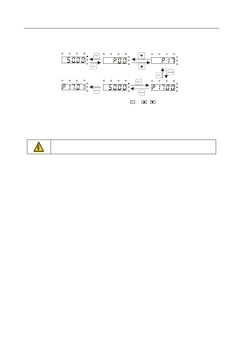
5.4.3 How to watch the inverter state through function codes
S1 series inverters provide group P17 as the state inspection group. Users can enter into P17 directly
to watch the state.
All digits are
blinking.
The ones place is
blinking.
DATA
ENT
DATA
ENT
DATA
ENT
PRG
ESC
PRG
ESC
PRG
ESC
PRG
ESC
The ones place is blinking.
The ones place is blinking.
The ones place is blinking.
Note: When setting the value, you can press and + to modify the value.
»
SHIFT
Fig 5.6 Sketch map of state watching
5.5 Basic operation instruction
5.5.1 What this section contains
This section introduces the function modules inside the inverter
Ensure all the terminals are fixed and tightened firmly.
Ensure the motor matches with the inverter power.
5.5.2 Common commissioning procedures
The common operation procedures are shown below (take motor 1 as an example).

 Loading...


