S1 series standard inverter
-22-
Note:
1. The fuse, DC reactor, brake unit, brake resistor, input reactor, input filter, output reactor and
output filter are optional parts. See Chapter 12 Optional peripheral accessories for details.
2. P1 and (+) have been short connected by default for 400V 132kW and above inverters. If users
need to connect to external DC reactor, take off the short-contact tag of P1 and (+).
3. When connecting the brake resistor, take off the yellow warning sign marked with PB, (+) and (-)
on the terminal block before connecting the brake resistor wire, otherwise, poor contact may
occur.
4. 400V 45–55kW inverter can support both optional built-in brake unit and external brake unit.
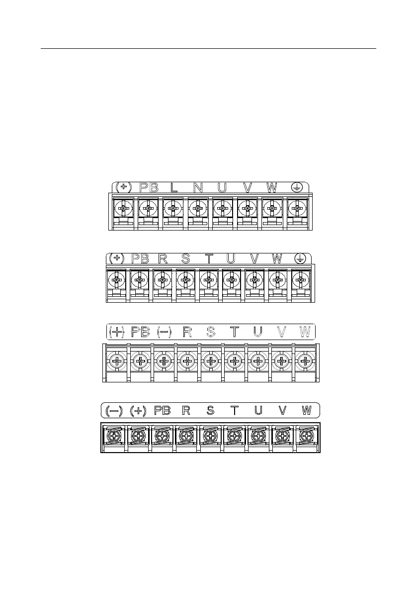
4.3.2 Main circuit terminal diagram
Fig 4.9 1PH 230V 0.4–2.2kW
Fig 4.10 3PH 400V 0.75–2.2kW
Fig 4.11 3PH 400V 4–22kW
Fig 4.12 3PH 400V 30–37kW
 Loading...


