15.
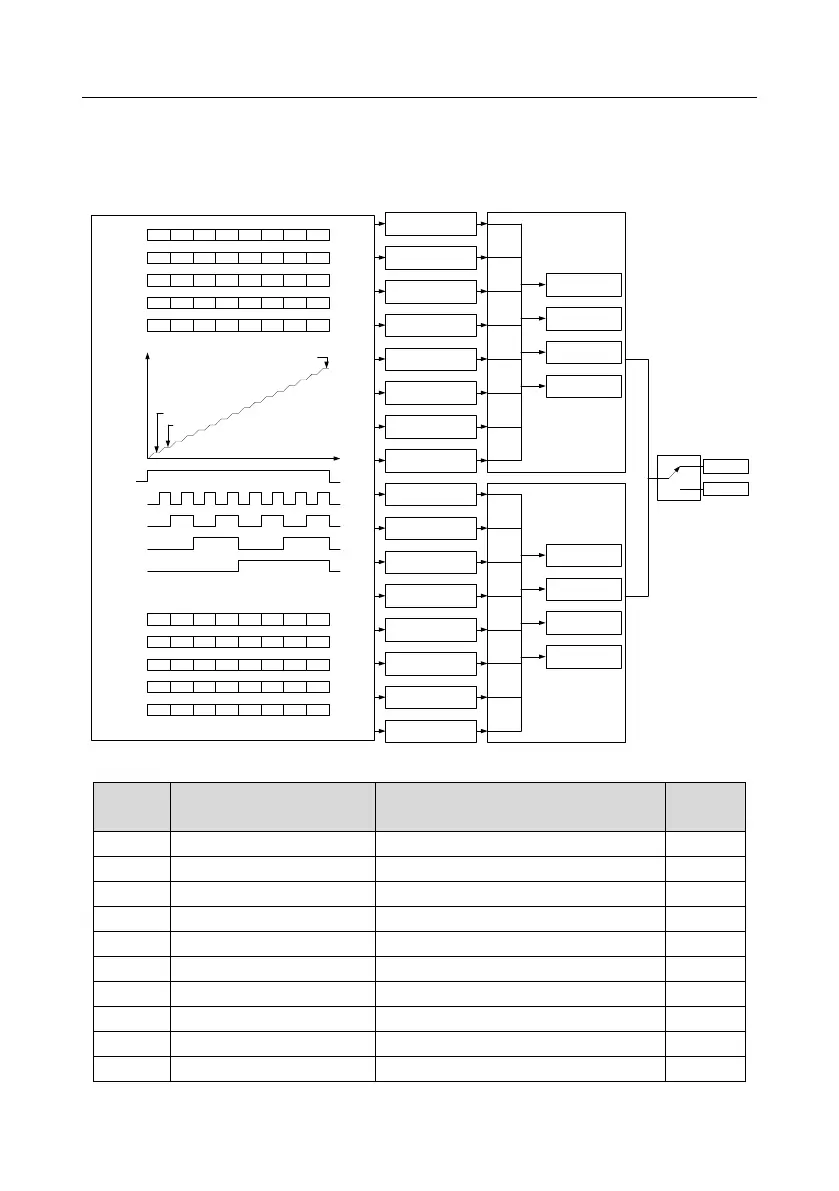
P10.02 multi-step speed 0
P10.03 running time of 0
th
step
P10.04 multi-step speed 1
P10.05 running time of 1
st
step
P10.06 multi-step speed 2
P10.07 running time of 2
nd
step
P10.08 multi-step speed 3
P10.09 running time of 3
rd
step
P10.10 multi-step speed 4
P10.11 running time of 4
th
step
P10.12 multi-step speed 5
P10.13 running time of 5
th
step
P10.14 multi-step speed 6
P10.15 running time of 6
th
step
P10.16 multi-step speed 7
P10.17 running time of 7
th
step
P10.18 multi-step speed 8
P10.19 running time of 8
th
step
P10.20 multi-step speed 9
P10.21 running time of 9
th
step
P10.22 multi-step speed 10
P10.23 running time of 10
th
step
P10.24 multi-step speed 11
P10.25 running time of 11
th
step
P10.26 multi-step speed 12
P10.27 running time of 12
th
step
P10.28 multi-step speed 13
P10.29 running time of 13
th
step
P10.30 multi-step speed 14
P10.31 running time of 14
th
step
P10.32 multi-step speed 15
P10.33 running time of 15
th
step
BIT0
BIT1
BIT2
BIT3
BIT4
BIT5
BIT6
BIT7
BIT8
BIT9
BIT10
BIT11
BIT12
BIT13
BIT14
BIT15
Terminal function 16
Multi-step speed
terminal 1
Terminal function 17
Multi-step speed
terminal 2
Terminal function 18
Multi-step speed
terminal 3
Terminal function 19
Multi-step speed
terminal 4
P10.34
Acceleration/deceleration time
selection of 0–7 section of
simple PLC
P00.10 acceleration time 1
P00.12 deceleration time 1
P08.00 acceleration time 2
P08.01 deceleration time 2
P08.02 acceleration time 3
P08.03 deceleration time 3
P08.04 acceleration time 4
P08.15 deceleration time 4
00
01
10
11
BIT0
BIT1
BIT2
BIT3
BIT4
BIT5
BIT6
BIT7
BIT8
BIT9
BIT10
BIT11
BIT12
BIT13
BIT14
BIT15
P00.10 acceleration time 1
P00.12 deceleration time 1
P08.00 acceleration time 2
P08.01 deceleration time 2
P08.02 acceleration time 3
P08.03 deceleration time 3
P08.04 acceleration time 4
P08.15 deceleration time 4
00
01
10
11
P10.35
Acceleration/deceleration time
selection of 8–15 section of
simple PLC
Multi-step speed
output
Running command
Multi-step speed 0
Multi-step speed 1
Multi-step speed 15
ON
OFF
OFF ON
Terminal function 16
Multi-step speed
terminal 1
Terminal function 17
Multi-step speed
terminal 2
Terminal function 18
Multi-step speed
terminal 3
Terminal function 19
Multi-step speed
terminal 4
OFF ON OFF ON OFF ON
OFF ONOFF ON OFFON OFF ON
OFF ONOFF ONOFF ONOFF ON
Multi-step speed
8 9 10 11 12 13 14 15
ON ONON ON ON ONON ON
OFF ON
Terminal function 16
Multi-step speed
terminal 1
Terminal function 17
Multi-step speed
terminal 2
Terminal function 18
Multi-step speed
terminal 3
Terminal function 19
Multi-step speed
terminal 4
OFF ON OFF ON OFF ON
OFF ONOFF ON OFFON OFF ON
OFF ONOFF ONOFF ONOFF ON
OFF OFF OFF OFF OFF OFF OFF OFF
Multi-step speed
0 1 2 3 4 5 6 7
Frequency-hold
Valid
Invalid

 Loading...