10 Electrical wiring
System wiring diagram
TCGB0136 rev.1 - 05/2021
105
10
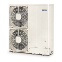
DSW6: No setting is required (do not change)
Factory setting
RAS-(4-6)H(V)(R/N)C2E RAS-(4-6)H(V)(R/N)P2E
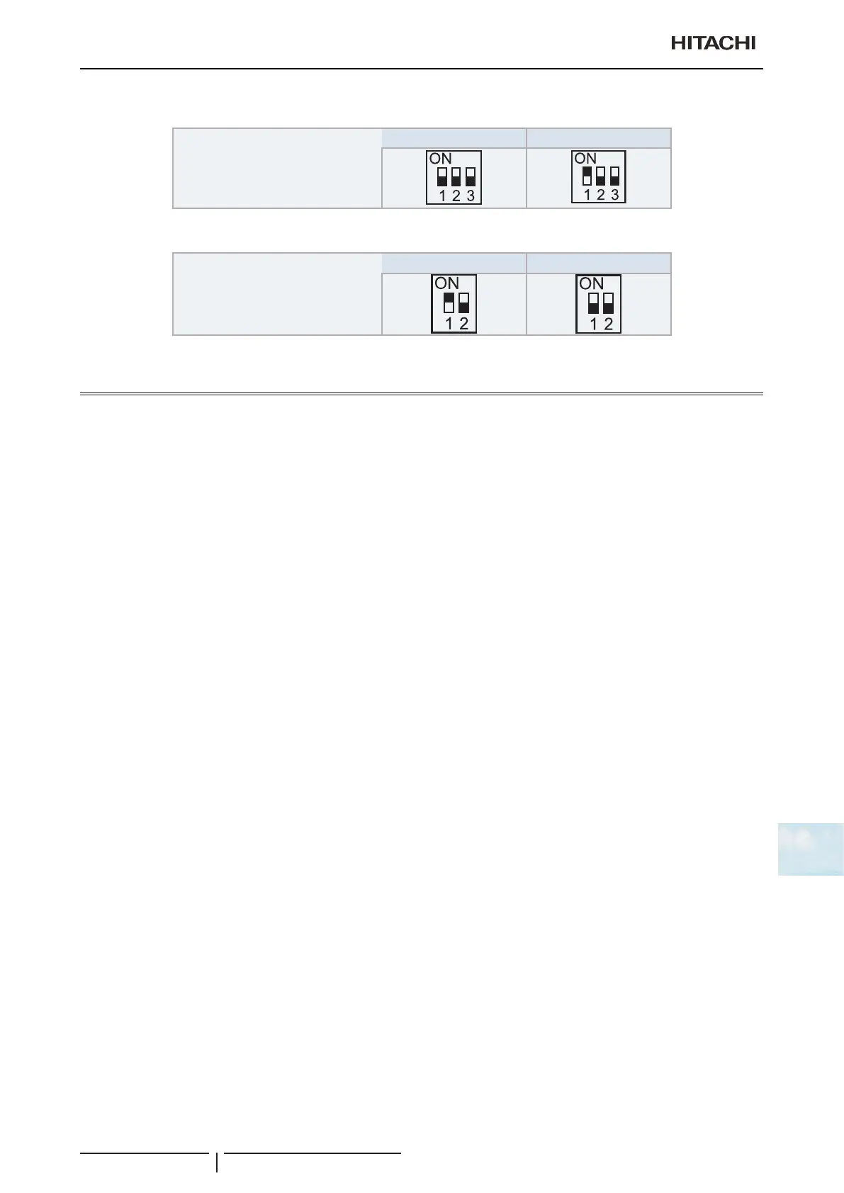
DSW7: No setting is required (do not change)
Factory setting
RAS-(4-6)H(V)(R/N)C2E RAS-(4-6)H(V)(R/N)P2E
10.4 System wiring diagram
10.4.1 Outdoor and indoor unit electrical wiring
• Connecttheelectricalwiresbetweentheindoorunitandtheoutdoorunitasshowinthegure.
• When installing the electrical wiring, follow local codes and regulations.
• The refrigerant piping and the control wiring are connected to the units in the same refrigerant cycle.
• Use shielded twisted pair cable (more than 0.75 mm
2
) for operation wiring between the outdoor unit and indoor unit,
and operation wiring between indoor unit and indoor unit.
• Use a 2-core wire for the operating line (do not use wire with more than 3 cores).
• Use shielded wires for intermediate wiring to protect the units from noise interference at lengths of less than 300 m.
The size must comply with local code.
• Open a hole near the connection hole of power source wiring when multiple outdoor units are connected from a
single power source line.
• The recommended breaker sizes are detailed in the “10.4.2Wiresize” section.
• Inthecasethataconduittubeforeld-wiringisnotused,xrubberbusheswithadhesiveonthepanel.
• Alleldwiringandequipmentmustcomplywithlocalandinternationalcodes.
• H-LINK twist pair shielded cable must be grounded in the outdoor unit side.

 Loading...