9 Piping work and refrigerant charge
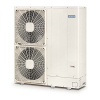
Refrigerant piping range
TCGB0136 rev.1 - 05/2021
88
ืืืื
20m
ื
30m
IU1
IU4
IU3
IU2
OU1
OU1
ื
3m
ื
3m
ื
3m
ื
3m
ื3m
? NOTE
Allpicturesareasexample.Branchandheadersarenotshowedasrealsizesorrealpicture,fortheinstallationofthiscomponentsfollow
thetechnicaldocumentation.
9.2.4 Combinations of piping size and piping length
Liquid
Ø6.35 Ø9.52 Ø12.70 Ø15.88
Gas
Ø9.52 Ø12.70 Ø15.88 Ø19.05 Ø12.70 Ø15.88 Ø19.05 Ø22.20 Ø25.40 Ø15.88 Ø19.05 Ø22.20 Ø25.40 Ø28.58 Ø22.20 Ø25.40 Ø28.58
3 HP -
30
(1) (2)
30
(2)
- 30
(1)
50 - - - - - - - - - - -
4 - 5 - 6 HP - - 5
(2)
5
(2)
40
(1)
75 50
(4)
- - 30
(3)
30
(3) (4)
- - - - - -
(1).Reducinggaspipesizewilllowercoolingcapacityduetolargerpressurelossingaspipingandnarrowoperationrange.
(2).Reducingliquidpipesizewillnarrowoperationrangeduetoindoorunitrelationwithexpansionvalvecapacity.
(3).Increasingliquidpipesizewillrequireadditionalrefrigerantcharge.
(4).WhenusingØ19.05gaspipe(soft-annealed),pleaseswitchONDSW2-4#intheOutdoorUnitPCB.
Default combination
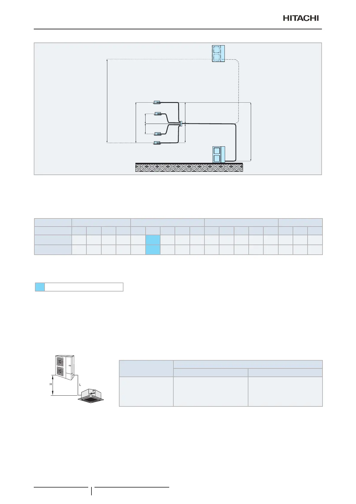
9.2.5 Refrigerant piping size and multikit/distributor
Select the piping connection sizes according to the following procedures
• Between outdoor unit and branch pipe: Select the same pipe connection size as the pipe size of the outdoor unit.
• Between branch pipe and indoor unit: Select the same pipe connection size as the pipe size of the indoor unit.
1 indoor unit system
(mm)
Outdoor Unit HP
Pipe Size (L)
Gas Liquid
3 - 6 Ø15.88 Ø9.52

 Loading...