10 Electrical wiring
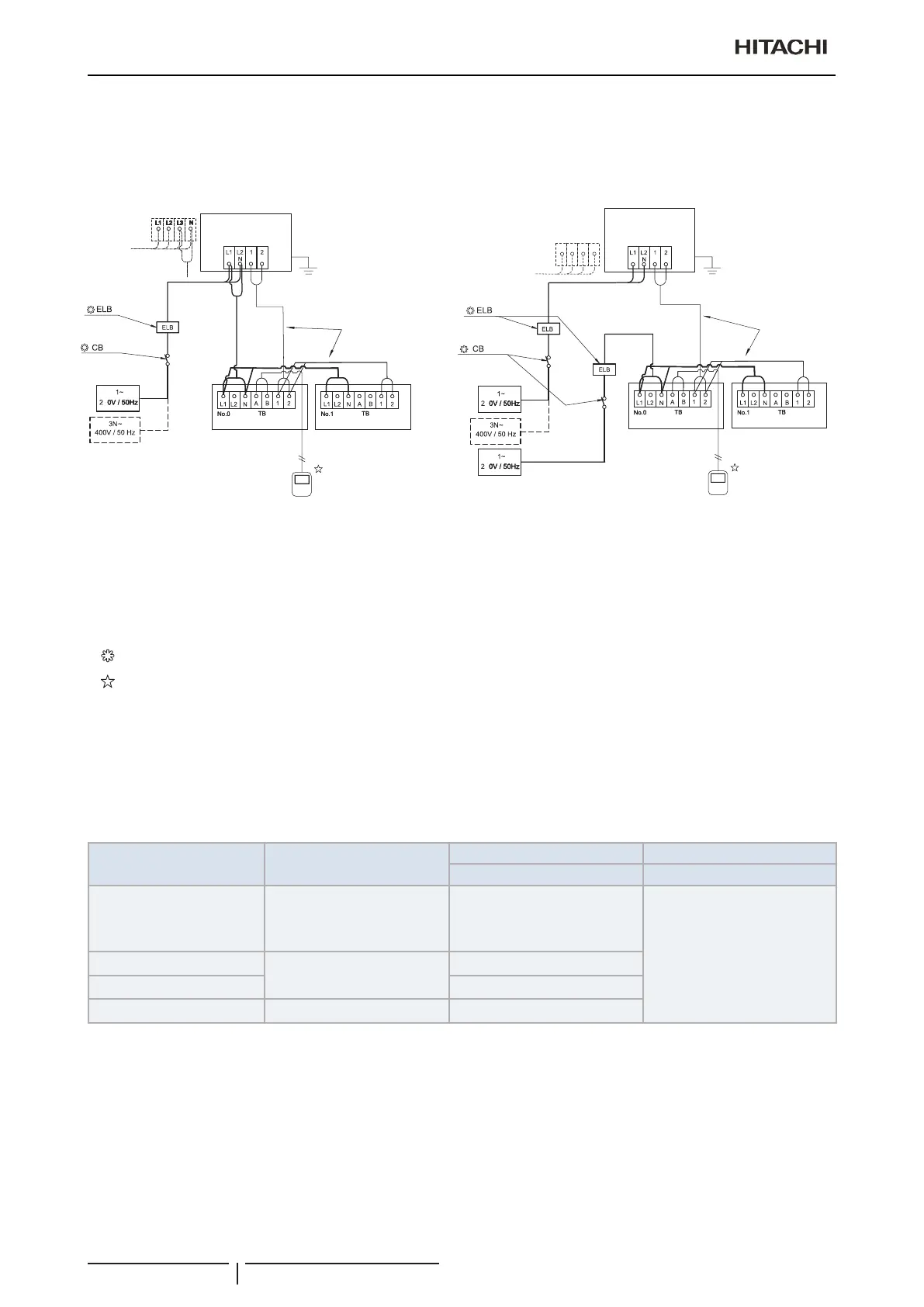
System wiring diagram
TCGB0136 rev.1 - 05/2021
106
? NOTE
Takecarewiththeconnectionoftheoperatingline.IncorrectconnectionmaycauseafailureofthePCB.
Power source from the outdoor unit to the indoor unit Independent power source of outdoor unit and indoor unit
3
3
3
L1 L2 L3 NL1 L2 L3 N
L1 L2 L3 N
Number 0 System
Outdoor unit
Number 0 System
Outdoor unit
Operating Line
(Shielded Pair Cable)
DC5V (Non-Pole
Transmission,
H-LINK System)
Remote control switch
(Twisted shielded pair cable)
Operating Line
(Twisted Shielded
Pair Cable)
DC5V (Non-Pole
Transmission,
H-LINK System)
Indoor Unit
Remote control switch
(Twisted shielded pair
cable)
Indoor Unit
Indoor Unit
Indoor Unit
TB Terminal board
CB CircuitBreaker(eldsupplied)
ELB EarthleakageBreaker(eldsupplied)
A Power source from the outdoor unit to the indoor unit
___ Field Wiring
Field supplied
Optional Accessory
10.4.2 Wire size
Recommendedminimumsizesforeldprovidedwires:
Usewireswhicharenotlighterthantheordinarypolychloroprenesheathedexiblecord(codedesignation60245IEC
57).
Model Power supply
Power source cable size Transmitting cable size
EN60 335-1 EN60 335-1
All Indoor Units
(except 8, 10, 16 and 20HP)
1~ 230V 50Hz
or
1~ 220-240V 50Hz
(depending on the model)
0.75 mm²
0.75 mm²
RAS-3HVRC2
1~ 230V 50Hz
4.0 mm
2
RAS-(4-6)HV(R/N)(C/P)2E 6.0 mm
2
RAS-(4-6)H(R/N)(C/P)2E 3N~ 400V 50Hz 4.0 mm
2
? NOTE
Followlocalcodesandregulationswhenselectingeldwires,CircuitbreakersandEarthLeakagebreakers.

 Loading...