1-63
TROUBLESHOOTING
<Inverter Printed Circuit Board on ISPM>
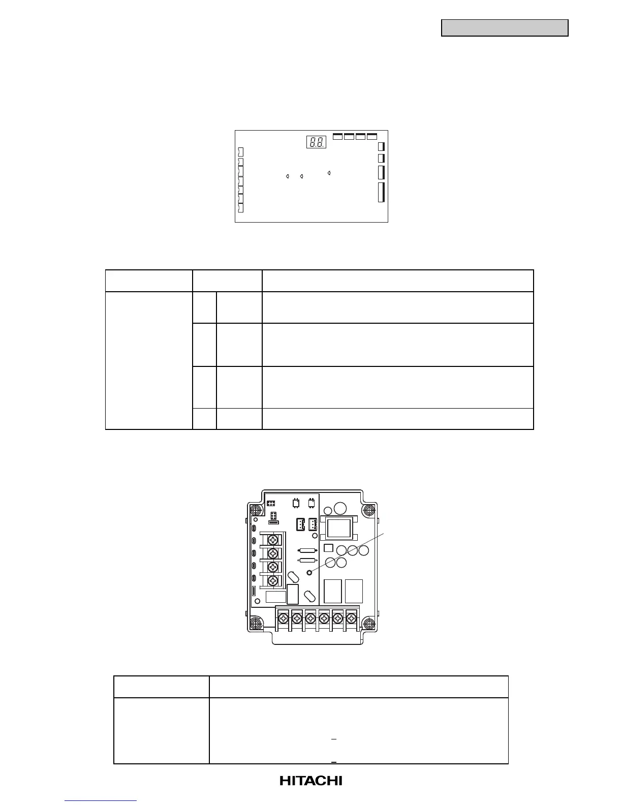
• LED Functions on Outdoor Unit ISPM
■ Dip Switches and LED Functions on Outdoor Unit Printed Circuit Boards
Name of Internal
Circuit Board
Controlling Board: 14 LED1 Power Source for PCB1
PCB1 (Red) Normal Condition: Activated
Abnormal Condition: Deactivated
15 LED2 This LED2 indicates the transmission state between the PCB1
and ISPM.
Normal Condition: Flickering
Abnormal Condition: Activated or Deactivated
16 LED3 This LED3 indicates the transmission state between the
(Yellow) indoor unit and outdoor unit.
Normal Condition: Flickering
Abnormal Condition: Activated or Deactivated
18 SEG1 This SEG1 indicate the following: "alarm", "protective safety
device has tripped" or "checking items".
Part Name Contents of Functions
Name of Printed
Circuit Board
* LED (Red) This indicates the voltage between both terminal of capacitor
201 CB1 and CB2 for inverter part.
Activated: The voltage between both terminals of capacitor,
CB is 50V
+20V or greater.
Deactivated: The voltage between both terminals of capacitor,
CB is 50V
+20V or smaller.
Function
TB3
RS W
RB
VTU
NPD P
TB2
R216
R215
ZN20
LED201
ZN202
R201
R200
CN207 CN206
CN9
PC207
C
PC208
CN8
RB
N
P
P1
LED201
ISPM
(2) Printed Circuit Board in Outdoor Unit
LED1 LED3
LED2
PCB for Outdoor Unit

 Loading...


