1-62
TROUBLESHOOTING
1.2.6 Function of LEDs
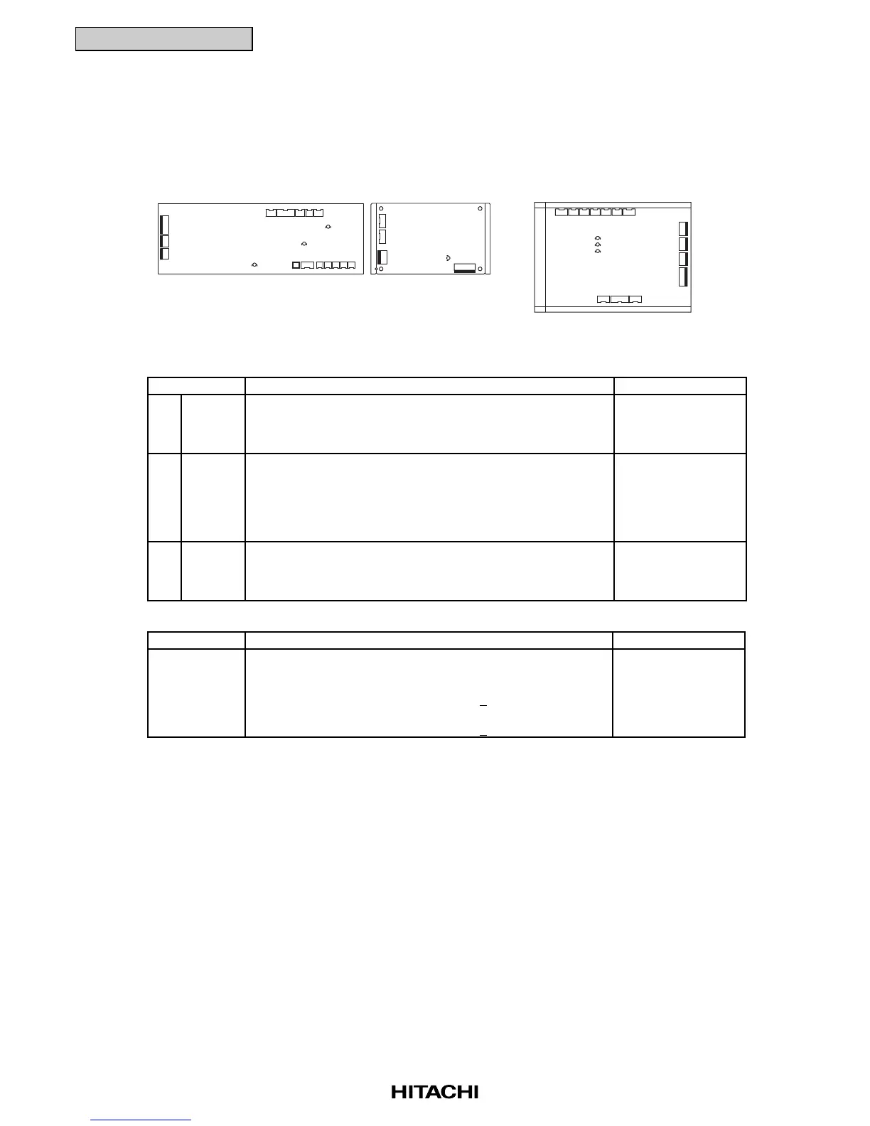
(1) Printed Circuit Board in Indoor Unit
( * Following figure shows a separated-board type PCB.)
■ LED Functions on Indoor Unit Printed Circuit Board for Control
■ LED Functions on Indoor Unit Printed Circuit Boards for Power Supply (PCB2 for RCI Series only)
Part Name Contents of Functions Remarks
1 LED1 This LED1 indicates the transmission state between
(Red) the indoor unit and remote control switch.
Normal Condition: Flickering
Abnormal Condition: Activated or Deactivated
2 LED3 This LED3 indicates the transmission state between
(Yellow) the indoor unit and outdoor unit.
Normal Condition: Flickering One Time/Some Seconds
Abnormal Condition: Activated or Deactivated more
than 30 seconds or Flickering
(30 times/1 second)
3 LED4 This LED4 indicates the power supply (5V) for
(Red) micro-computer.
Normal Condition: Activated
Abnormal Condition: Deactivated
-
-
-
Part Name Contents of Functions Remarks
This indicates the voltage between terminals of capacity
C1 on the PCB for DC fan motor.
Activated: The voltage between both terminals
of capacity, C is 50
+20V or greater.
Deactivated: The voltage between both terminals
of capacity, C is 50
+20V or smaller.
LED1
(Red)
-
RPI, RCD and RPC Series
LED3
LED1
LED4
LED3
LED1
LED4
PCB1
LED1
PCB2
RCI Series

 Loading...


