1-72
TROUBLESHOOTING
(a) Check the mounted part is broken or not by visual
check.
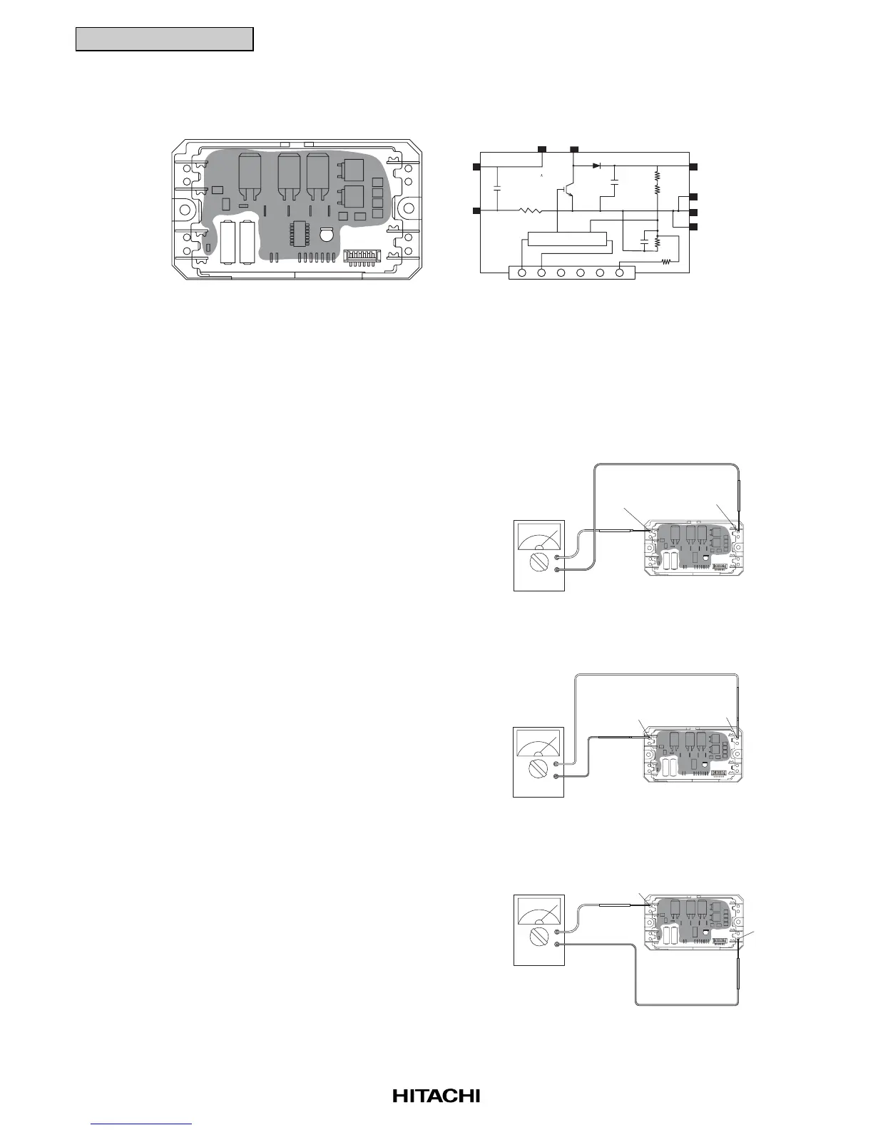
(b) By touching the + side of the tester to the L2 terminal
of ACT module and the - side of the tester to the P
terminal of ACT module, measure the resistance.
If all the resistances are greater than 100 kΩ, it is
normal.
(c) By touching the - side of the tester to the L2 terminal
of ACT module and the + side of the tester to the P
terminal of ACT module, measure the resistance.
If all the resistances are from 1 to 5 kΩ, it is normal.
(d) By touching the + side of the tester to the L2 terminal
of ACT module and the - side of the tester to the I
terminal of ACT module, measure the resistance.
If all the resistances are from 50 to 200 kΩ, it is
normal.
(3) Checking Procedures ACT Module (for 5HP only)
Outer Appearance and Internal Circuit of ACT Module
+
-
L2 P
Power Factor Control
L1 L2
(+)
(-)
P
N1
N2
I
Remove all the terminals of the ACT module before check.
If items (a) to (f) are performed and the results are satisfactory, the ACT module is normal.
Measure it under 1 kΩ range of a tester. Do not use a digital tester.
+
-
L2
P
+
-
L2
I

 Loading...


