[ CHAPTER 6 SCHEMATIC, CIRCUIT BOARD DIAGRAMS
1. Using schematic and circuit board diagrams
Model VM-E455LA is a minor version of the previously issued VM-E555LA; model VM-H655LA is a minor version
of the previous VM-H755LA.
This manual includes only the differences between VM-E455LAIH655LA and VM-E555LA/H755LA. For all other
items, refer to the type model sections of the previous manual, as shown in the table below.
- How to interpret the following table -
1. Circuit boards marked “Same as TYPExxx” are the same as those in the designated model.
2. For circuit boards marked “See TYPExxx”, see the diagrams of the designated model; for differences, see this
manual.
VCA board
SE
board EMQ board LCD board EMQ board
VM-E455LA See TYPE 555 This manual Same as TYPE 555 Same as TYPE 555 Same as TYPE 555
VM-H655LA
See TYPE
755
Same as TYPE
555 Same as TYPE 755
Same
as TYPE 755 Same as TYPE 755
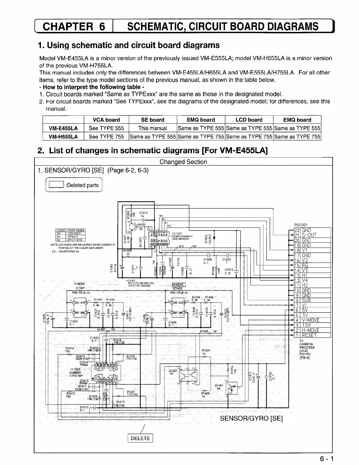
2. List of changes in schematic diagrams [For VM-E455LA]
Changed Section
1. SENSOR/GYRO [SE] (Page 6-2, 6-3)
PGIOOI
NOTE:VOLTAGES ARE MEASURED WHEN CAMERA IS
POINTED AT THE COLOR BAR CHART.
@ : WAVEFORMS No.
6-f