ENGLISH
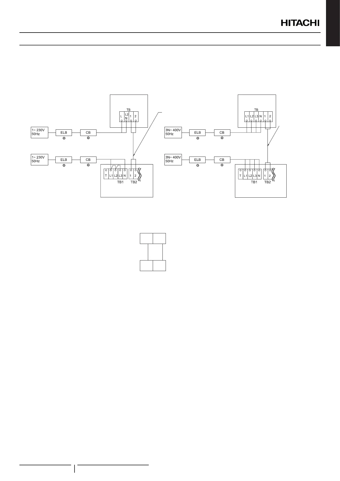
7.4 TERMINAL BOARD CONNECTIONS
7.4.1 Table board 1
Main power supply
The main power supply connection is wired to the Terminal board (TB1) as follows:
Operating Line
(Twisted shielded pair cable or shielded pair cable)
DC5V (Non-Pole Transmission, H-LINK system)
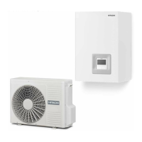
Outdoor unit
RAS-WHVNP(E)
YUTAKI S
YUTAKI S
Outdoor unit
RAS-WHNPE
Operating Line
(Twisted shielded
pair cable or
shielded pair
cable)
DC5V (Non-Pole
Transmission,
H-LINK system)
Indoor/outdoor communication wiring (TB2)
• The transmission is wired to terminals 1-2.
• The H-LINK II wiring system requires only two transmission cables that connect the indoor unit and the outdoor unit.
1
1
2
2
Indoor unit
Outdoor unit
• Use twist pair wires (0.75 mm²) for operation wiring between outdoor unit and indoor unit. The wiring must consist of 2-core wires
(Do not use wire with more than 3 cores).
• Use shielded wires for intermediate wiring to protect the units from noise interference, with a length of less than 300 m and a size
in compliance with local codes.
• In the event that a conduit tube for eld-wiring is not used, x rubber bushes to the panel with adhesive.
! CAUTION
Ensure that the transmission wiring is not wrongly connected to any live part that could be damaged the PCB.
ELECTRICAL AND CONTROL SETTINGS
PMML0335A rev.1 - 04/2016
103
 Loading...
