5 REFRIGERANT CYCLE AND HYDRAULIC CIRCUIT
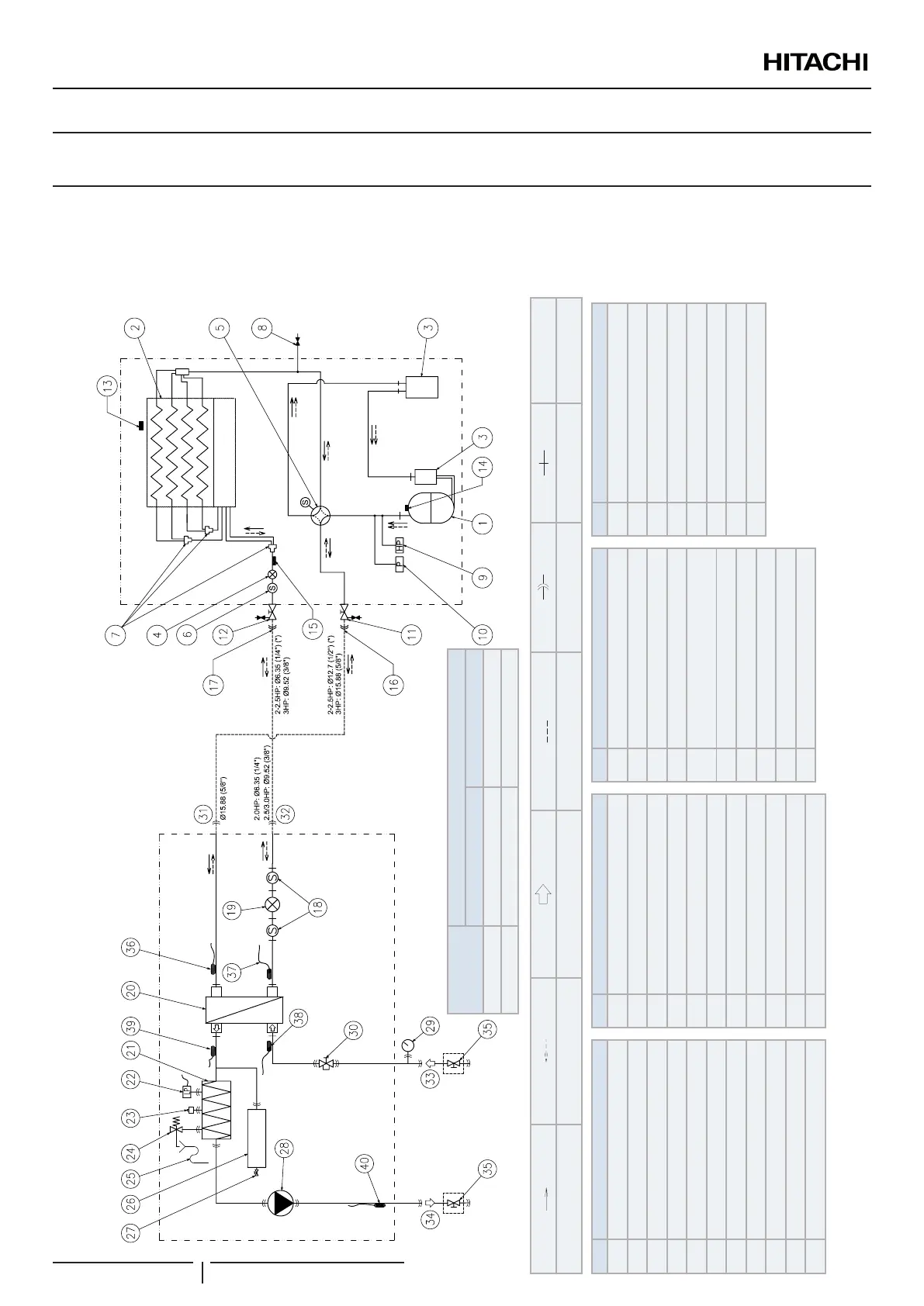
5.1 REFRIGERANT CYCLE AND HYDRAULIC CIRCUIT FOR SPLIT SYSTEM
5.1.1 YUTAKI S
RAS-(2-3)WHVNP + RWM-(2.0-3.0)NE
Refrigerant
Heating refrigerant ow Cooling refrigerant ow Water ow (Heating/Cooling) Field supplied piping line Flare nut connection Brazed connection R410A
Nº Part name
1 Compressor
2 Air side heat exchanger
3 Accumulator
4 OU electronic expansion valve
5 4-way valve
6 OU refrigerant strainer
7 Distributor
8 Refrigerant check joint
9 High pressure switch for protection
10 Pressure switch for control
11 Stop valve for gas line
Nº Part name
12 Stop valve for liquid line
13 Ambient thermistor
14 Discharge gas thermistor
15 Pipe thermistor
16 OU refrigerant gas connection
17 OU refrigerant liquid connection
18 IU refrigerant strainer
19 IU electronic expansion valve
20 Water side heat exchanger
21 Water electric heater
22 Low pressure switch
Nº Part name
23 Air purger
24 Safety valve
25 Drain pipe
26 Expansion vessel
27
Air valve for pressure regulation of
expansion vessel
28 Water pump
29 Manometer
30 Water strainer
31 IU refrigerant gas connection
32 IU refrigerant liquid connection
Nº Part name
33 Water inlet connection
34 Water outlet connection
35 Shut-off valve (Accessory)
36 Gas pipe thermistor (Heating)
37 Liquid pipe thermistor (Heating)
38 Water inlet thermistor
39 PHEX water outlet thermistor
40 Water outlet thermistor
Outdoor unit
YUTAKI S
? NOTE
(*): Use refrigerant pipe adapters factory supplied with the outdoor unit:
Model
Pipe adapter
Gas pipe Liquid pipe
2 HP Ø15.88→Ø12.7 -
2.5 HP Ø15.88→Ø12.7 Ø9.52→Ø6.35
REFRIGERANT CYCLE AND HYDRAULIC CIRCUIT
PMML0335A rev.1 - 04/2016
76
 Loading...
