b. Installation of the ATW-RTU-04
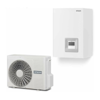
In case of setting an installation with 2 circuits (circuit 1 and circuit 2) and the same demand ON/OFF is used for both of
them, remove the jumper between terminals 13 and 14 of the Terminal board 2 and connect the RF receiver as shown in the
following picture.
Thermostat requirements:
• Power supply: 230V AC
• Contact voltage: 230V
13 14
13 14
Jumper
Common
Line
Demand ON/OFF
Receiver input 2
? NOTE
• If wireless intelligent thermostat is selected, optional ON/OFF thermostat has no effect.
• Set the conguration in the user’s control. See chapter “8 UNIT CONTROLLER” for more information.
• In case of setting an installation with 2 circuits (Circuit 1 and Circuit 2) and a different Demand ON/OFF is used for each of them, please refer to
“Input terminals (Optional input functions)” section in this chapter.
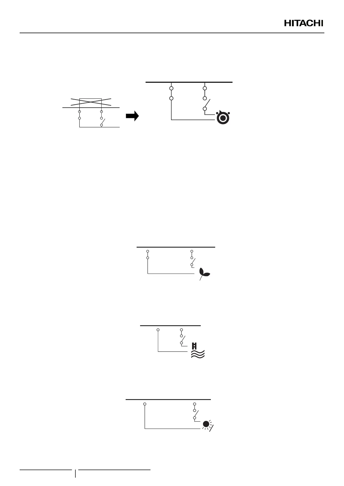
ECO (input 2)
When enabled at Unit controller, both for circuit 1 and Circuit 2, also for heating and cooling, this input switches the unit to the
temperature congured.
The input can come from a push button, a thermostat or any other external device with that purpose.
Common
Line
ECO
Input 2
13 15
Swimming pool (input 3)
When it is necessary to control the temperature of the swimming pool water, a connection between the heat pump and the
corresponding sensor must be done on terminals 16 and 17 at the Terminal board (input 4).
16 17
Common
Line
SWP
IN
Input 3
Solar (input 4)
This input comes from a solar panel sensor. The solar combination by input demand allows HSW to be heated by solar system when
there is enough solar energy available. The connection of this input signal has to be done between terminals 16 and 18 at TB2.
Common
Line
Solar
IN
Input 4
16 18
ELECTRICAL AND CONTROL SETTINGS
PMML0335A rev.1 - 04/2016
106
 Loading...
