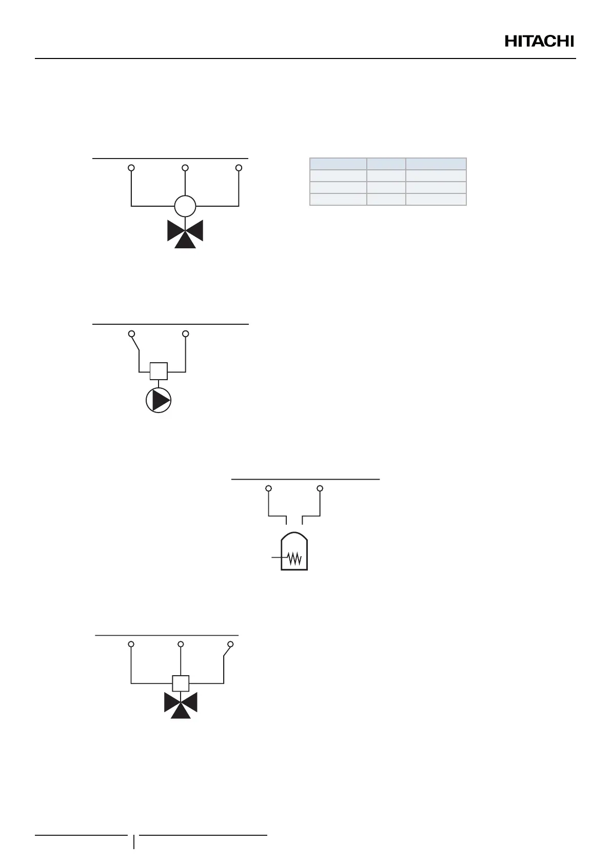
Output terminals (Default output functions)
Mixing valve for Circuit 2
The mixing valve is controlled to maintain the second heating temperature at the second heating temperature set point. The control
system decides how much to open or close the mixing valve to achieve the desired position of the valve.
24 25 26
M
(C)
(O)
(N)
Brown
Black
Blue
Mixing Valve
(Circuit 2)
Terminal Name Description
24 C Close
25 O Open
26 N Neutral
Valve requirements:
• Power supply: 230V AC 50Hz
• Maximum running current: 100mA
Water pump 2 Circuit 2
In case of a second circuit installation (second temperature level) the secondary pump is the circulating pump for the second heating
temperature.
26
(N)
M
27
(L)
Water pump II
(Circuit 2)
Pump requirements:
• Power supply: 230V AC 50Hz
• Maximum running current: 500mA (An auxiliary relay must be
installed in case of high consumption of the water pump).
Electrical heater DHWT output
In those cases where a DHW tank is installed with an electrical heater, the Air to Water heat pump can activate the electric heater of
the tank when the heat pump cannot achieve the required DHW temperature by itself.
(N)
31
Electrical
Heater
DHWT (EH
4
)
(L)
30
3 Way valve for DHW tank output
Yutaki units can be used to heat DHW. The signal is used on a 3-way motorized diverting valve and to provide control of supply
water ow (water ow for space heating when there is no signal, and water ow for DHW when signal is ON)
M
(L)
32
(C)
Brown
Black Blue
33 34
3WV / DHW
DHWT
Valve requirements:
• Power supply: 230V AC 50Hz
• Maximum running current: 100mA
! CAUTION
Only 3-way type valve can be connected:
• Spring return 2-wire type 3-way valve: the 3-way valve should be tted when normally working (not power to the valve). Normally diverts to heating
circuit side.
• When using SPST 3-wire valve, HITACHI is not responsible for its operation.
ELECTRICAL AND CONTROL SETTINGS
PMML0335A rev.1 - 04/2016
108
 Loading...
