Do you have a question about the Hobart H600 and is the answer not in the manual?
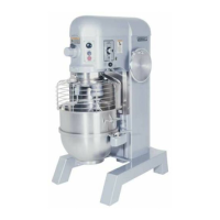
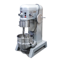
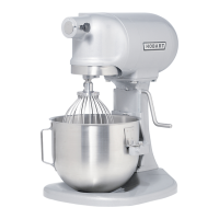
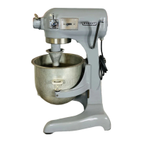
Provides an overview of the Hobart H600, L800, and P660 mixers and their applications.
Details electrical specifications and motor ratings for H600, L800, and P660 models.
Table detailing lubricant types and quantities for various mixer components.
Step-by-step instructions for draining the transmission oil from the mixer.
Detailed steps for removing the planetary assembly from the mixer.
Information on bowl guard addition and identification of different styles.
Steps required to remove the bowl guard assembly from the mixer.
Steps for removing the old style bowl guard switch assembly.
Procedures for installing the old style bowl guard switch.
Steps required to remove the top cover assembly from the mixer.
Steps to disassemble the agitator shaft from the planetary assembly.
Steps for disassembling the planetary oil pump assembly.
Steps required to remove the internal gear from the transmission housing.
Notes regarding changes in clutch shaft, planetary shaft, and attachment hub assemblies.
Instructions for installing the planetary shaft assembly into the transmission.
Steps to disassemble the worm gear shaft assembly.
Adjusting the sleeve to find the motor shaft bind point.
Details changes in clutch shaft assembly design, including stepped spacers.
Removing the upper clutch and gear assemblies from the shaft.
Steps to remove the top spacer from the clutch shaft.
Steps to remove and disassemble the planetary shaft assembly.
Installation steps for the planetary shaft assembly on H600/L800 models.
Procedure to replace the shear key for the attachment hub.
Disassembling the transmission to access and remove the attachment hub.
Steps required to remove the gear selector assembly from the mixer.
Procedures for assembling and installing the gear selector.
Steps required to remove the shifter yokes from the mixer.
Description and resolution for oil leaks past the front motor bearing.
Making alignment marks on motor components for reassembly.
Methods to check motor capacitors using a meter or substitution.
Procedure for checking and adjusting motor rotor shaft alignment.
Procedure for placing the alignment tool on L800 shafts.
Assembling the terminal board and capacitor brackets for motor replacement.
Procedure for adjusting the mixer's brake for proper operation.
Steps to increase the mixer's braking action.
Tables of resistance values for testing three-phase motors.
Procedures for testing motor capacitors for functionality.
Steps required to remove the bowl support from the mixer.
Adjusting the bowl lift nut assembly to prevent back-driving.
Adjusting the screw located under the bowl support for clearance.
Procedures for checking the bowl height sensing feature.
Steps required to remove manual bowl lift components.
Steps for removing and disassembling the manual bowl lift screw assembly.
Adjusting the lift screw end play for proper operation.
Adjusting the Flexa-Gear belt for the power bowl lift.
Procedures for testing motor current draw for the power bowl lift.
Information on the electronic timer's availability and upgrade kits.
Using preset keys for timed mixing operations.
Steps required to disassemble the switch plate assembly.
Steps to enter service diagnostics mode for the timer.
Steps to exit service diagnostics mode.
Descriptions of various electrical components like capacitors, contactors, switches.
Definitions of common electrical symbols used in wiring diagrams.
Diagrams illustrating power flow in H600 and L800 transmissions.
Lists common mechanical symptoms and their possible causes.
Lists common electrical symptoms and their possible causes.
| Capacity | 60 quarts |
|---|---|
| Transmission | Gear-driven |
| Manufacturer | Hobart |
| Category | Mixer |
| Type | Floor Mixer |
| Voltage | 208-240V |