OM-227 978 Page 13
SECTION 5 − INSTALLATION
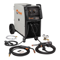
5-1. Installing Nozzle, Contact Tip, And Adapter
Ref. 243 839-A
! Turn off welding power
source.
1 Nozzle
2 Contact Tip
3 Tip Adapter
. Wire size stamped on tip − check
and match wire size.
Tools Needed:
8 mm
Head
Tube
8 mm
1
3
2
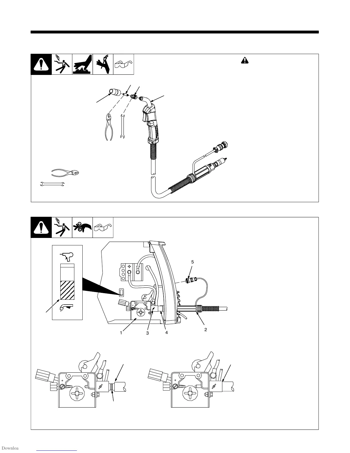
5-2. Installing Welding Gun
804 695-A
1 Drive Assembly
2 MIG Gun
3 Gun Securing Thumbscrew
4 Gun End
Loosen thumbscrew. Insert end
through opening until it bottoms
against drive assembly. Tighten
thumbscrew.
Welding gun must be inserted
completely to prevent leakage of
shielding gas.
5 Gun Trigger Plug
Insert plug into receptacle, and
tighten threaded collar.
6 Spool Gun/MIG Gun Switch
Place switch in MIG Gun position.
Close door.
CorrectIncorrect
. Be sure that gun end is tight against drive assembly.
3
Gun Fully Seated
3
Gun Not Seated
Exposed O-rings
will cause shielding
gas leakage.
Spool Gun
MIG Gun
6
5
1
3
2
4