OM-227 978 Page 19
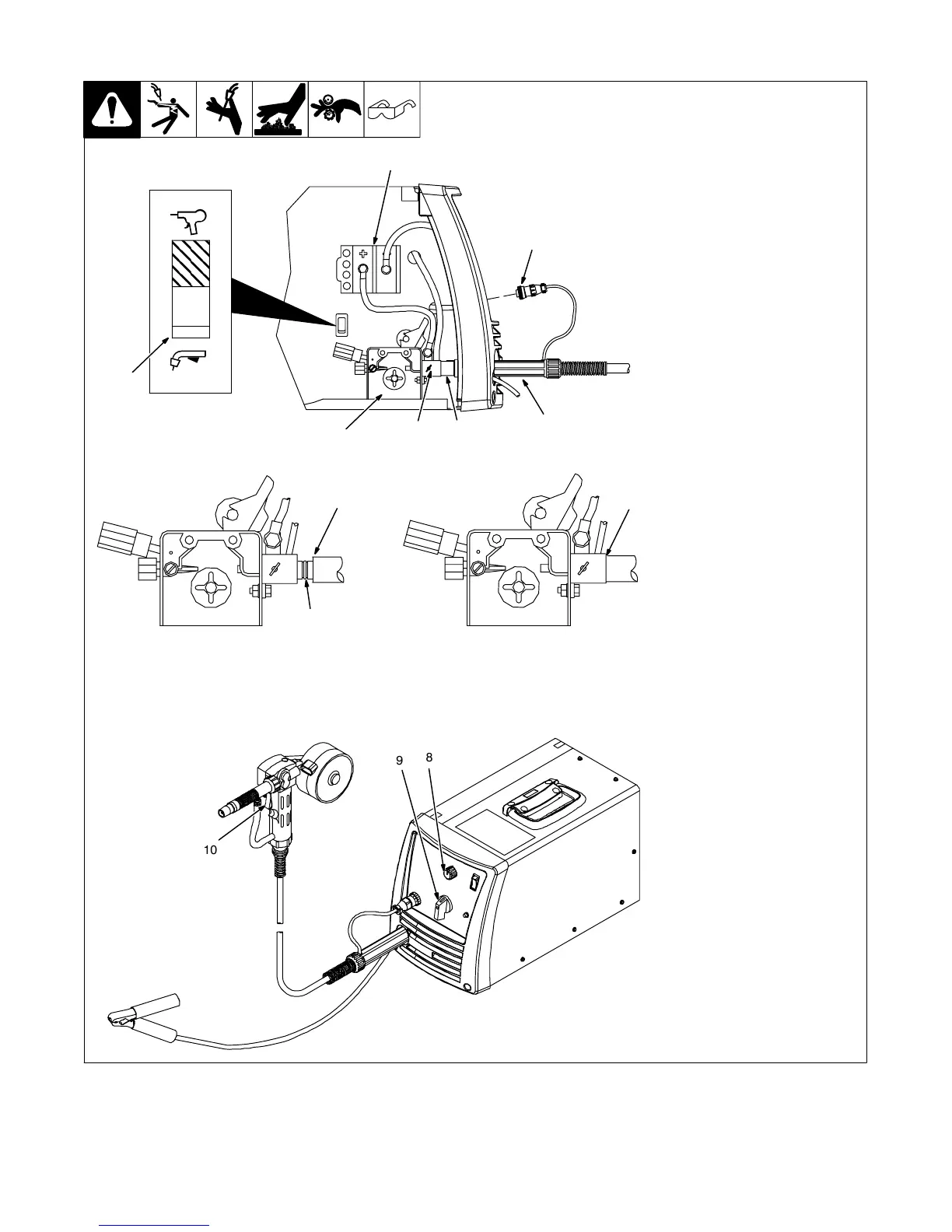
5-11. Connecting Optional Spool Gun
804 695-A / 804 696-A
1 Drive Assembly
2 Spool Gun
3 Gun Securing Thumbscrew
4 Gun End
Loosen thumbscrew. Insert end
through opening until it bottoms
against drive assembly. Tighten
thumbscrew.
Spool gun must be inserted
completely to prevent leakage of
shielding gas.
5 Gun Trigger Plug
Insert plug into receptacle, and
tighten threaded collar.
6 Spool Gun/MIG Gun Switch
Place switch in Spool Gun position.
7 Polarity Changeover Terminal
Block
To make proper polarity connection,
see welding power source Owner’s
Manual.
Close door.
8 Wire Feed Speed Control
Wire feed speed is controlled by
welding power source Wire Speed
control (see welding power source
Owner’s Manual or door chart for
appropriate setting).
9 Voltage Control
Arc voltage is controlled by welding
power source Voltage control (see
welding power source Owner’s
Manual or door chart for
appropriate setting).
10 Trigger
Press trigger to energize welding
power source contactor, start
shielding gas flow, and begin wire
feed.
CorrectIncorrect
. Be sure that gun end is tight against drive assembly.
3
Gun Fully Seated
3
Gun Not Seated
Exposed O-rings
will cause shielding
gas leakage.
5
1
3
2
4
Spool Gun
MIG Gun
6
7
10
8
9