OM-227 978 Page 27
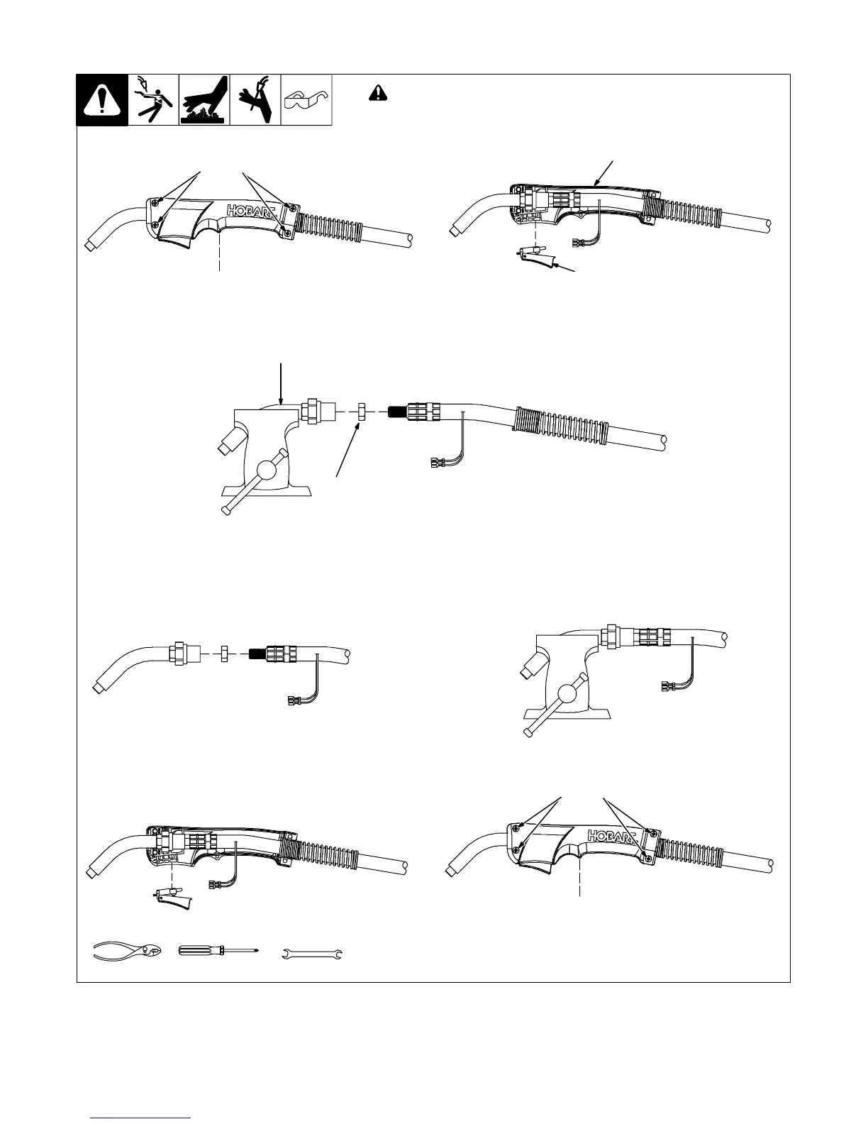
7-6. Replacing Switch And/Or Head Tube
243 840-A
Tools Needed:
15 mm
Remove screws (5)
and nuts (4).
Remove handle halves.
Hand-tighten head tube into cable connector.
Place head tube in vice and tighten until
nuts are tight.
Remove from vice. Reposition handle halves, and
install switch housing.
! Turn Off welding power source
/wire feeder and disconnect gun.
Remove switch housing. Install new
switch and connect leads (polarity is
not important). Reassemble in
reverse order. If replacing head tube,
continue to end of figure.
12
3
8
6
7
Remove screw on
opposite side.
Secure head
tube in vice.
Loosen jam nut.
Remove from vice
and turn head tube
out by hand.
4
5
phillips
Reinstall screws
and nuts.
9
Reinstall screw on
opposite side.