❏ 3. Locate the two pre-bent, non-threaded
pushrod wires and the three threaded, pre-bent
pushrod wires. The
rudder pushrod will use one
threaded, and one non-
threaded wire. The elevator
pushrod will use one non-threaded and two
threaded wires.
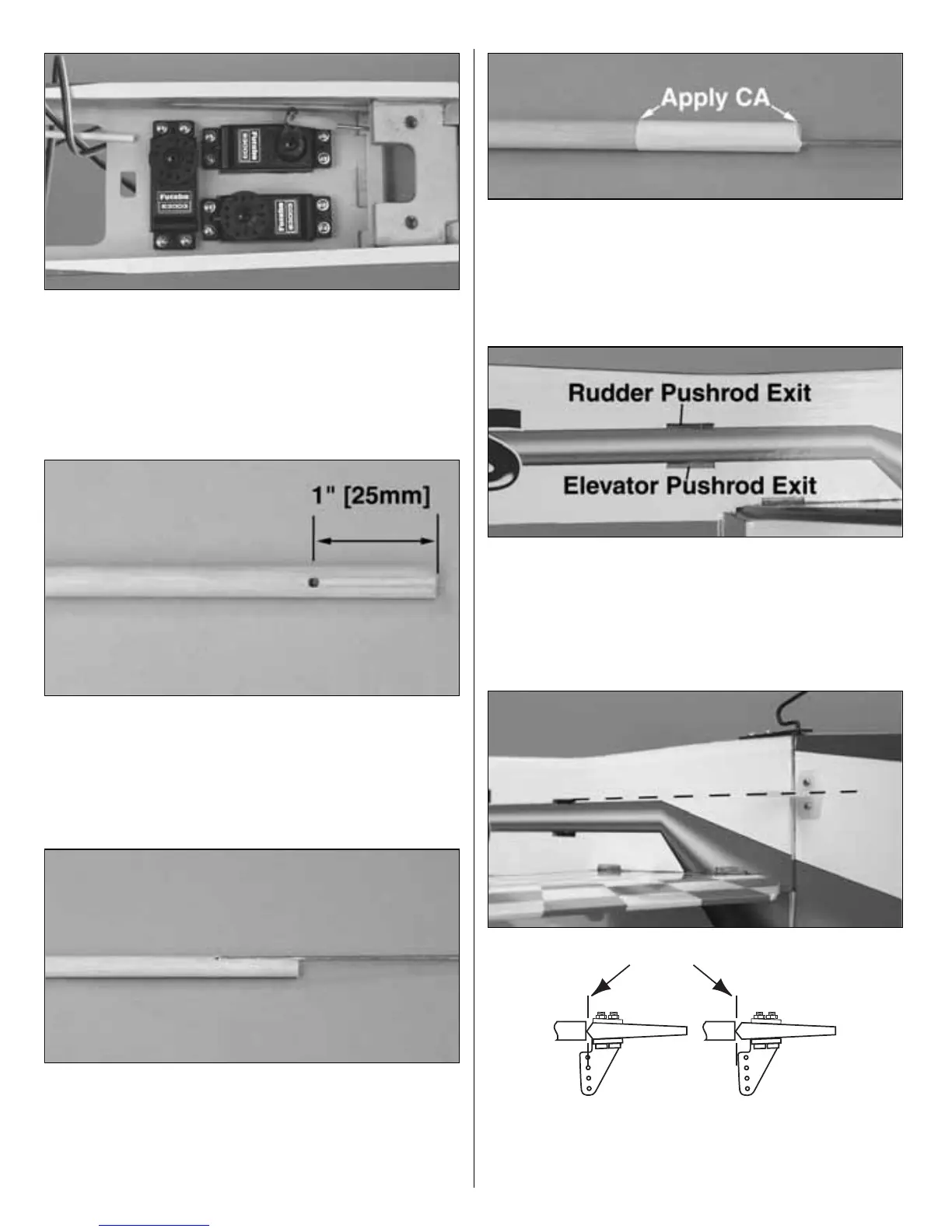
❏ 4. Drill a 5/64" [2mm] hole 1" [25mm] in from
both ends of each pushrod. Cut a groove in the
dowel from the hole to the end of the dowel. For
the elevator, one end will be grooved on either side
to accept two pushrod wires.
❏ 5. Insert the bent end of one threaded piece of
wire into one end of each pushrod. (Two for the
elevator
pushrod.) Insert the bent end of the non-threaded
wires into the other end of each pushrod. CA the
wires in place.
❏ 6. Cut the heat shrink tubing into 1-1/2" [38mm]
lengths. Use the heat shrink tubing at each end of
the pushrod to hold everything in place as shown
in the photo. Apply a few drops of thin CA to each
end of the heat shrink tubing to secure it.
❏ 7. Use a sharp hobby knife to remove the
covering
from the pushrod exits. The photo shows both the
rudder and elevator exits cut out on the right side
of the fuselage. Remove only the covering from the
elevator exit on the left side.
❏ 8. Install the rudder nylon control horn in line
with the pushrod exit. Hold the horn in position and
 Loading...