as shown in the photo. We added a Great Planes
Switch Mount & Charge Jack (GPMM1000, not
included) for convenience and ease of use at the
field, installed on the side of the fuselage. At this
time, it is suggested to allow the receiver and
battery the option of being moved until after the
aircraft has been balanced. Once balanced, the
receiver and battery should be secured into the
aircraft to prevent them from moving during flight.
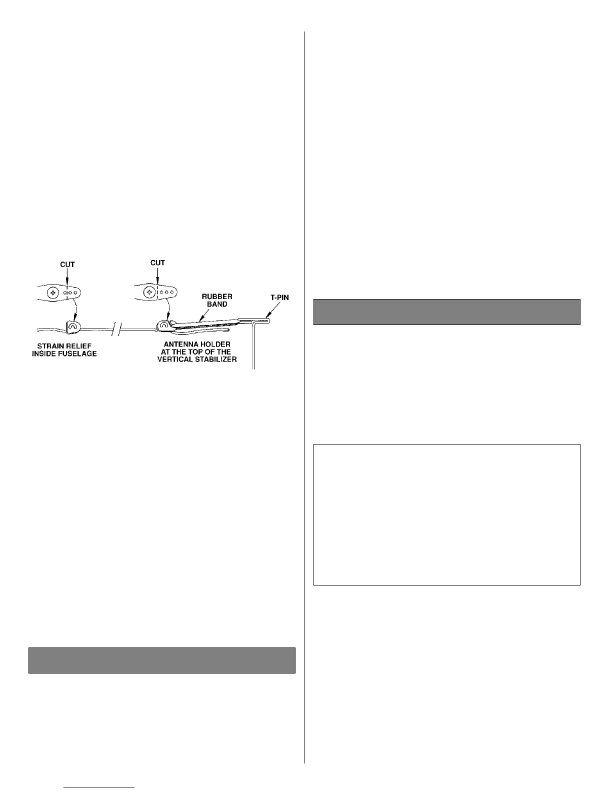
❏ 2. Route the antenna to the tail of the model.
You may use your preferred method or the method
we use in the Great Planes model shop. Drill a
15/64" hole through the fuse side in the proximity
of the receiver. Cut a 1/2" long piece of fuel tubing
and install it in the hole. Install a strain relief (as
shown in the sketch), then route the antenna
through the fuel tubing to the bottom of the fuse at
the tail. Use a rubber band to attach the antenna to
a T-pin at the aft end of the
fuselage. Do not cut or
shorten the antenna wire. Leave
any excess to
hang free.
By moving the position of the clevis at the control
horn toward the outermost hole, you will decrease
the amount of throw of the control surface. Moving
it toward the control surface will increase the
amount of throw. If these adjustments don’t
accomplish the job, you may need to work with a
combination of adjustments by also repositioning
the pushrod at the servo end. Moving the pushrod
towards the center of the servo horn will decrease
the control surface throw - outward will increase it.
Note: Throws are measured at the widest part of
the elevators, rudder and ailerons. If your radio
does not have dual rates, set the control throws to
halfway between the specified high and low rates.
We recommend the following control surface
throws as a starting point:
One leading cause of crashes is flying an airplane
with its control throws set differently from those
recommended in
the instructions. The Great Planes
AccuThrow
™
(GPMR2405) lets you quickly and
easily measure actual throws first, so you can
make necessary corrections before you fly. Large,
no-slip rubber feet provide a firm grip on covered
surfaces without denting or marring the finish.
Spring tension holds AccuThrow’s plastic ruler
steady by each control surface. Curved to match
control motions, the ruler provides exact readings
High Rate Low Rate
Elevator 5/16" [8mm] Up 3/16" [5mm] Up
5/16" [8mm] Down 3/16" [5mm] Down
Rudder 1" [25mm] Right 5/8" [16mm] Right
1" [25mm] Left 5/8" [16mm] Left
Ailerons 3/8" [9.5mm] Up 1/4" [6.5mm] Up
3/8" [9.5mm] Down 1/4" [6.5mm] Down
Control Surface Throws
Control Throw Adjustment
24
 Loading...