as above.
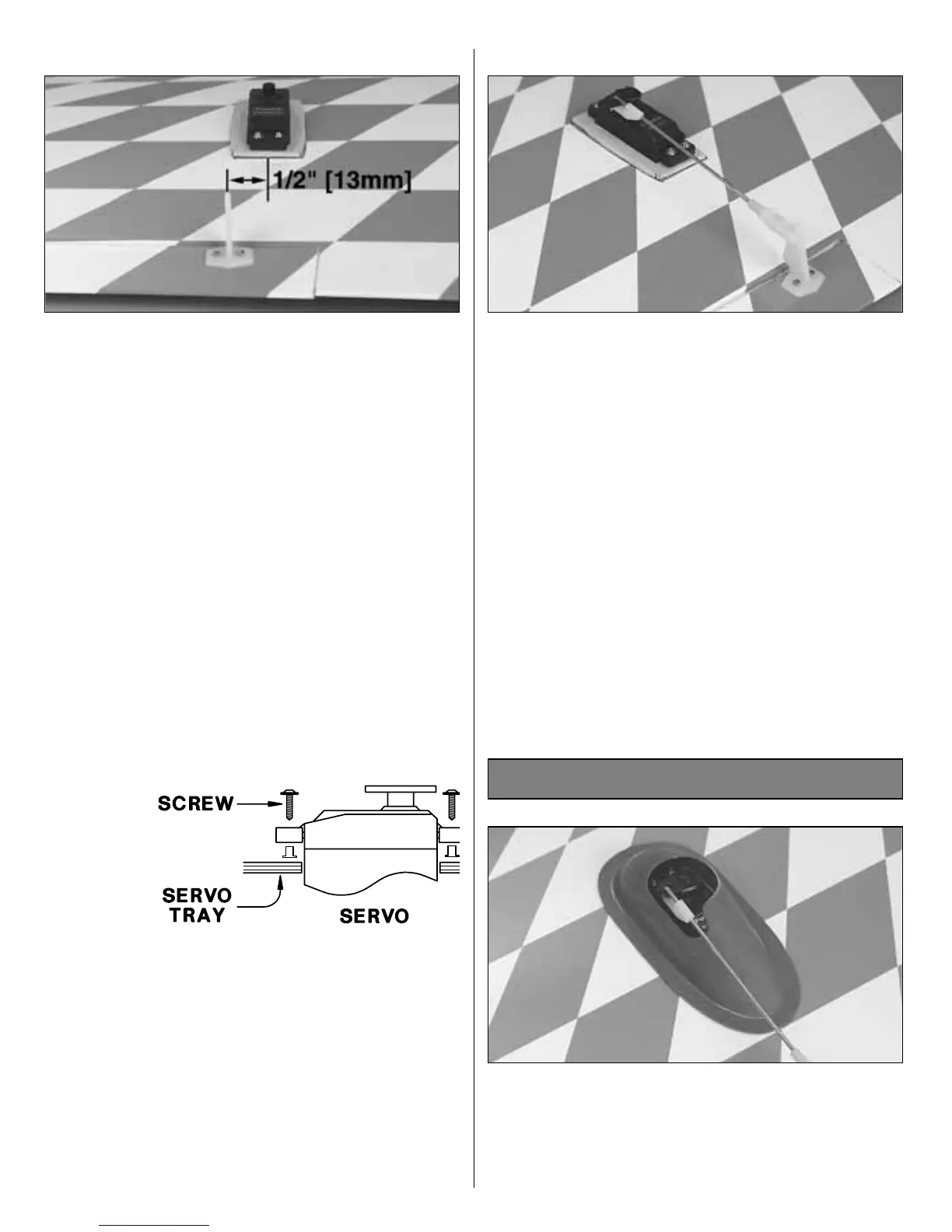
❏ 24. Install the aileron nylon control horns. The
control horns are positioned 1/2" [13mm] towards
the tip of the wing from the centerline of the servo.
Hold the horn in position and mark the location of
the mounting holes. Drill 3/32" [2.4mm] mounting
holes through the marks. Wick two to three drops
of thin CA into the holes to harden the underlying
balsa, then re-drill the holes. Attach the horns
using four 2mm x 15mm machine screws and two
nylon nut plates. Do not over-tighten the screws,
crushing the underlying balsa.
❏ 25. Connect the aileron servos to the receiver,
turn on the radio, then center the servo horn. The
servo horns should be facing opposite each other
as shown in the sketch if you are planning on using
a “Y” harness for the aileron servos or a computer
radio. Place a clevis retainer onto a clevis. Thread
the clevis 14 turns onto one of the 7-7/8" [200mm]
pushrods. Attach the clevis to the second hole
from the outside hole on the control horn.
❏ 26. Attach the clevises to the second hole from
the top of the control horns. Center the ailerons,
then mark the pushrods at the point where they
meet the holes on the servo arm. Make a 90-
degree bend in the wires at this mark. Cut off the
excess wire 3/8" [9.5mm] above the bend. Enlarge
the servo horn holes with a 5/64" [2mm] drill bit.
Insert the bent wire pushrods into the servo horn,
then secure them with nylon pushrod keepers.
❏ 1. Test fit the aileron servo covers. Carefully trim
any portion of the covers that interfer with the
operation of the aileron pushrods and servo horns.
Tape the covers into position. Wick thin CA
between the cover and wing to secure each of
Final Assembly
17
 Loading...