20 FKS 315-2000 E | Version 1.11
Care, Maintenance and Repair
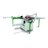
Fig. 49: Set the distance of the cutting blade to the saw blade
Step 6: Screw the separating knife with a distance bet-
ween 3 mm and 8 mm from the saw blade.
Step 7: Secure the saw blade guard.
9.2.4Changing the drive belt
Step 1: Disconnect the power plug from the socket.
Step 2: Remove the saw blade, s. Section "saw blade
change".
Step 3: Remove the chip container by unscrewing the 3
M8x18 screws.
Fig. 50: Replace drive belt
Step 4: Unscrew the 4 screws of the left cover and re-
move the cover.
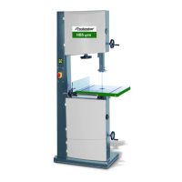
Fig. 51: Release engine screws
Step 5: Loosen the 4 M8x40 hexagon head cap screws
A and the engine B turnbolt B, and then loosen
and remove the drive belt.
Step 6: Install the new drive belt and reassemble the saw
in reverse order.
9.2.5Changing the drive belt of the auxiliary
saw blade
Step 1: Disconnect the power plug from the socket.
Step 2: Set the saw blade inclination angle to 0 ° (90 ° to
the saw table) and move the saw blade up as far
as possible.
Step 3: Unscrew the 4 screws of the right cover and re-
move the cover.
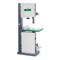
Fig. 52: Replace the drive belt of the auxiliary saw blade.
Step 4: Push the tensioner as far as possible in the direc-
tion of the arrow.
Step 5: Replace the old drive belt with a new drive belt
and reassemble the saw in reverse order.
9.2.6Aligning the sliding carriage
Step 1: Disconnect the power plug from the socket.
Step 2: Set the saw blade inclination angle to 0 ° (90 ° to
the saw table) and move the saw blade up as far
as possible.
Step 3: Mark the center of the saw blade with a felt tip
pen.
NOTE!
When removing the lower two M8x18 screws, the in-
clination angle is tilted to 30 °, when removing the up-
per M8x18 screw, the inclination angle is tilted to 0 °.
NOTE!
This process requires a precision ruler, a felt-tip pen,
and the assistance of a second person in addition to
the tool provided.