25
Operation
If you are already using
HomematicIP devices in your
smart home system or if you want
to combine your HomematicIP
Wired devices with wireless
HomematicIP components, you
can also connect the
HomematicIP Wired devices to an
(installed) Access Point. Therefore,
connect the HomematicIP Wired
Access Point to the (installed)
HomematicIP Access Point, as
described in the operating. After
-
wards, please proceed as descri-
bed above to connect the blind
actua
tor.
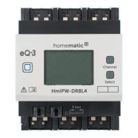
7 Operation
Via the following push-buttons, simple
operating functions are available di-
rectly on the device:
• system button (A)
• channel button (B)
• select button (C)
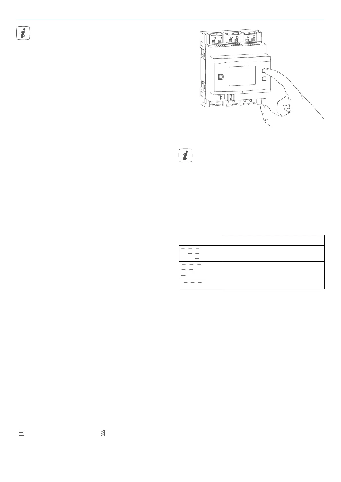
System button
By pressing the system button briefly
(see „Figure 9“ on page 24), you can
activate the LCD background lighting
of all devices connected to the bus.
Channel button
By pressing the channel button briefly,
you can select the desired channel. On
each button press, you can switch to
the next channel.
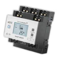
The selected channel is indicated by
the flashing symbol. The current height
(
) and slats positions ( ) of the selec-
ted channel are shown in the display
(alternating):
Figure 10
After switching on the blind actu-
ator, the blinds/shutters/awnings
are in an unknown position. The
current height and slats position
of a channel until reaching a limit
switch cannot be displayed. Du-
ring this time, the current moving
direction will be displayed:
Symbol Meaning
Move down
Moved up
Stop
Select button
After selecting a channel via the chan-
nel button (see Channel button), you
can select the channel condition by
briefly pressing the select button (move
down - stop - move up - stop etc.) (see
„Figure 11“ on page 26). On each
button press, you can switch to the next
condition.
If you have not selected a channel, you
can select the following options in the
LC display by pressing the Select button
briefly:
• bus supply voltage (in V)
• temperature in blind actuator (in °C)
• empty display
 Loading...