21
Start-up
rigid cable
[mm²]
flexible cable
without ferrule [mm²]
0,75 - 2,50 0,75 - 2,50
6.2 Selecting the supply voltage
Voltage supply of the blind actuator is
established only via the HomematicIP
Wired bus. The bus is supplied by the
HomematicIP Wired Access Point
(HmIPW-DRAP) (please refer to the
user manual of the HmIPW-DRAP).
The maximum total current consump-
tion of the blind actuator is as follows:
I
ges
= 100 mA
6.3 Mounting and installation
Please read this entire section
before starting to install the de-
vice.
To install the blind actuator on a DIN
rail within a distribution board, please
proceed as follows:
• Disconnect the power distribution
panel and cover any live parts, if
required (see hazard information).
OFF
Figure 2
• Remove the cover of the power
distribution panel.
• Place the blind actuator onto the
DIN rail. Make sure that you can
read the letters on the device and
display and that the connecting
terminals of channel 1 and 2 are at
the top.
1
2
Figure 3
• Make sure that the catch spring en-
gages properly and that the device
is securely seated on the rail.
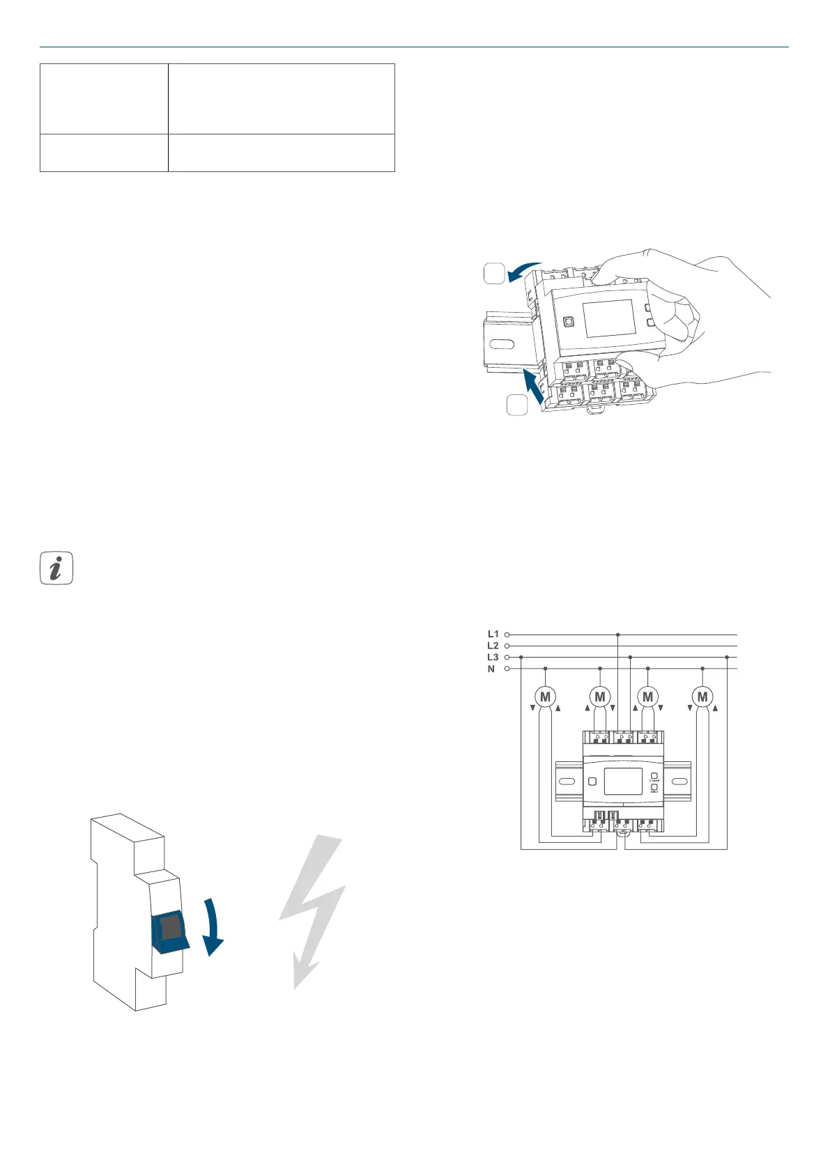
• Wire the device according to the
connecting diagram
Figure 4
• Connect the phase conductor for
the selected channel to the corres-
ponding terminal (G) (see figure 4).
Any types of phase conductors (L1,
L2, L3) can be connected to the
power input terminals.
• Connect the switched phase con-
ductor to move up the motor for the
selected channel to the correspon-
 Loading...