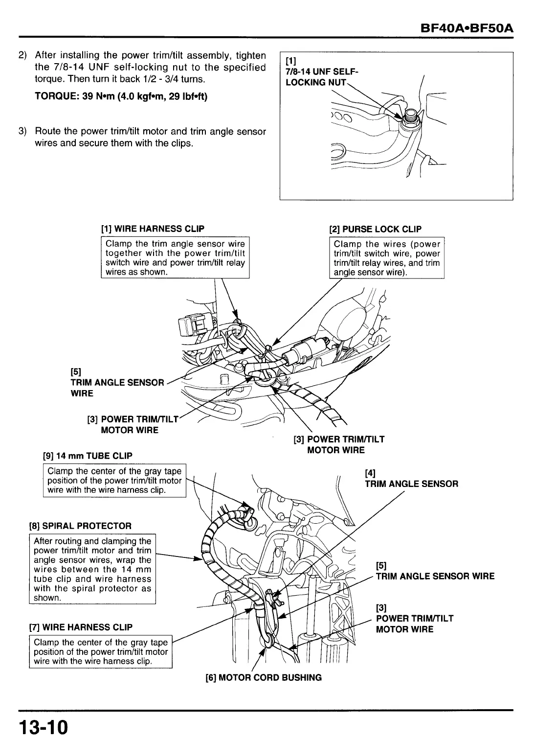
2)
After installing the power trim/tilt assembly, tighten
the
7/8-14
UNF
self-locking nut to the specified
torque. Then turn it back
1/2
-
3/4
turns.
TORQUE:
39
N*m
(4.0
kgfom,
29
Ibfoft)
3)
Route the power trim/tilt motor and trim angle sensor
wires and secure them with the clips.
11
1
7/8-14
UNF
SELF-
LOCKING NUT,
I
[l] WIRE HARNESS CLIP
Clamp the trim angle sensor wire
together with the power trimhilt
switch wire and power trimhilt relay
wires as shown.
[2]
PURSE LOCK CLIP
trim/tilt switch wire, power
trimhlt relay wires, and trim
151
TRIM ANGLE SENSOR
WIRE
[3] POWER TRIMITILT’
/--A/
I
MOTOR WIRE
[3] POWER TRIMITILT
[9] 14
mm
TUBE CLIP
MOTOR WIRE
141
((
TRIM ANGLE SENSOR
Clamp the center
of
the gray tape
position
of
the power trimhilt motor
wire with the wire harness cliD.
,
I
SPIRAL PROTECTOR
angle sensor wires, wrap the
wires between the
14
mm
TRIM ANGLE SENSOR
POWER TRIMITILT
MOTOR WIRE
[6] MOTOR CORD BUSHING
WIRE
13-1
0
 Loading...