CLIF-CBUSLC INTERFACE – INSTALLATION & COMMISSIONING INSTRUCTIONS
EN1Z-1026GE51 R0417 12
MOUNTING/DISMOUNTING
Before Installation
IMPORTANT
To allow the evaporation of any condensation resulting from low shipping / storage temperatures, keep the device at room
temperature for at least 24 h before applying power.
US requirement, only: This device must be installed in a UL-listed enclosure offering adequate space to maintain the
segregation of line voltage field wiring and Class 2 field wiring.
In the case of vertical mounting on DIN rails, the CLIF-CBUSLC should be secured in place using a commercially-available
stopper. See also the CLIF-CBUSLC – Mounting Instructions (MU1Z-1006GE51).
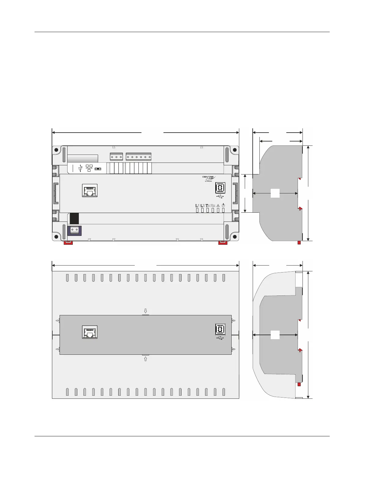
Dimensions
24
25 26
27
28 29 30 31 32
24V-0
24V~
1
GND1
485-1+
485-1-
n.a.
n.a.
GND2
485-2+
485-2-
n.a.
2
J1 J8
RS232
RS485-1
END
BIAS
MID
215.5
110
5245
49.5
57.5
Fig. 12. CLIF-CBUSLC (shown: model with onboard I/Os), dimensions (in mm)
147
57.5
215.5
J1 J8
52
Fig. 13. CLIF-CBUSLC with covers, dimensions (in mm)
NOTE: Use of the covers (MVC-80-AC1) obstructs access to the Ethernet and USB 2.0 Host Interfaces and RS232 socket.

 Loading...