CLIF-CBUSLC INTERFACE – INSTALLATION & COMMISSIONING INSTRUCTIONS
5 EN1Z-1026GE51 R0417
Bus and Port Connections
Overview
WARNING
Risk of electric shock or equipment damage!
► Do not touch any live parts in the cabinet!
► Disconnect the power supply before making connections
to or removing connections from terminals of the CLIF-
CBUSLC
► Do not reconnect the power supply until you have
completed installation.
► It is prohibited to power the CLIF-CBUSLC with the same
transformer used to power controllers or other devices
(e.g., the PW M-Bus Adapter).
► Observe the rules regarding electrostatic discharge.
24 25 26 27 28 29 30 31 32
24V-0
24V~
1
6 7
4
5
GND1
485-1+
485-1-
n.a.
n.a.
GND2
485-2+
485-2-
n.a.
2
J1 J8
1
8
2
3
RS232
RS485-1
END
BIAS
MID
9
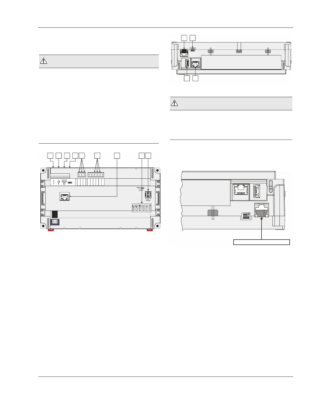
Fig. 2. Top view
Legend
1 RS232 / RJ45 socket (for factory debugging)
2 USB 2.0 Host Interface (for connection of the IF-
LON2); max. 500 mA, high speed
3 Ethernet / RJ45 socket (for SUSI communication);
10/100 Mbit/s; 1 "link" LED and 1 "activity" LED
4 Three-position slide switch (for setting bias and ter-
mination resistance of RS485-1: MUST REMAIN IN
MIDDLE POSITION!)
5 RS485-1 (isolated; for C-Bus communication)
6 RS485-2 (non-isolated; DO NOT USE)
7 Future functionality
8 LEDs
9 USB 2.0 Device Interface (for connection to web
browser for setup)
1 4
3
J1 J8
2
Fig. 3. Side view
WARNING
Risk of electric shock or equipment damage!
► It is prohibited to connect any of the RJ45 sockets of the
CLIF-CBUSLC Interface to a so-called PoE-enabled device
("Power over Ethernet").
RS232 / RJ45 Socket
Via its RS232 / RJ45 socket, the CLIF-CBUSLC can be
connected to a terminal for debugging purposes.
RS232-RJ45 SOCKET
J1 J8
Fig. 4. RS232 / RJ45 socket
USB 2.0 Host Interface
Via its USB 2.0 Host interface, the CLIF-CBUSLC can be
connected to the IF-LON2 External Interface Adapter and thus
thus to L
ONWORKS networks. Max. 500 mA, high speed. See
also section "LonWorks Communications" on pg. 17.

 Loading...