CLIF-CBUSLC INTERFACE – INSTALLATION & COMMISSIONING INSTRUCTIONS
EN1Z-1026GE51 R0417 14
24 V~
24 V~0
LINE
L
N
CPU #1 CPU #2
CPU 2
NOISE-FREE EARTH GROUND
(ONLY ONE PER SYSTEM)
N, L
EARTH GROUND
USB 2.0
Device Interface
!
REVERSED
POLARITY!
SHORT-CIRCUITING!
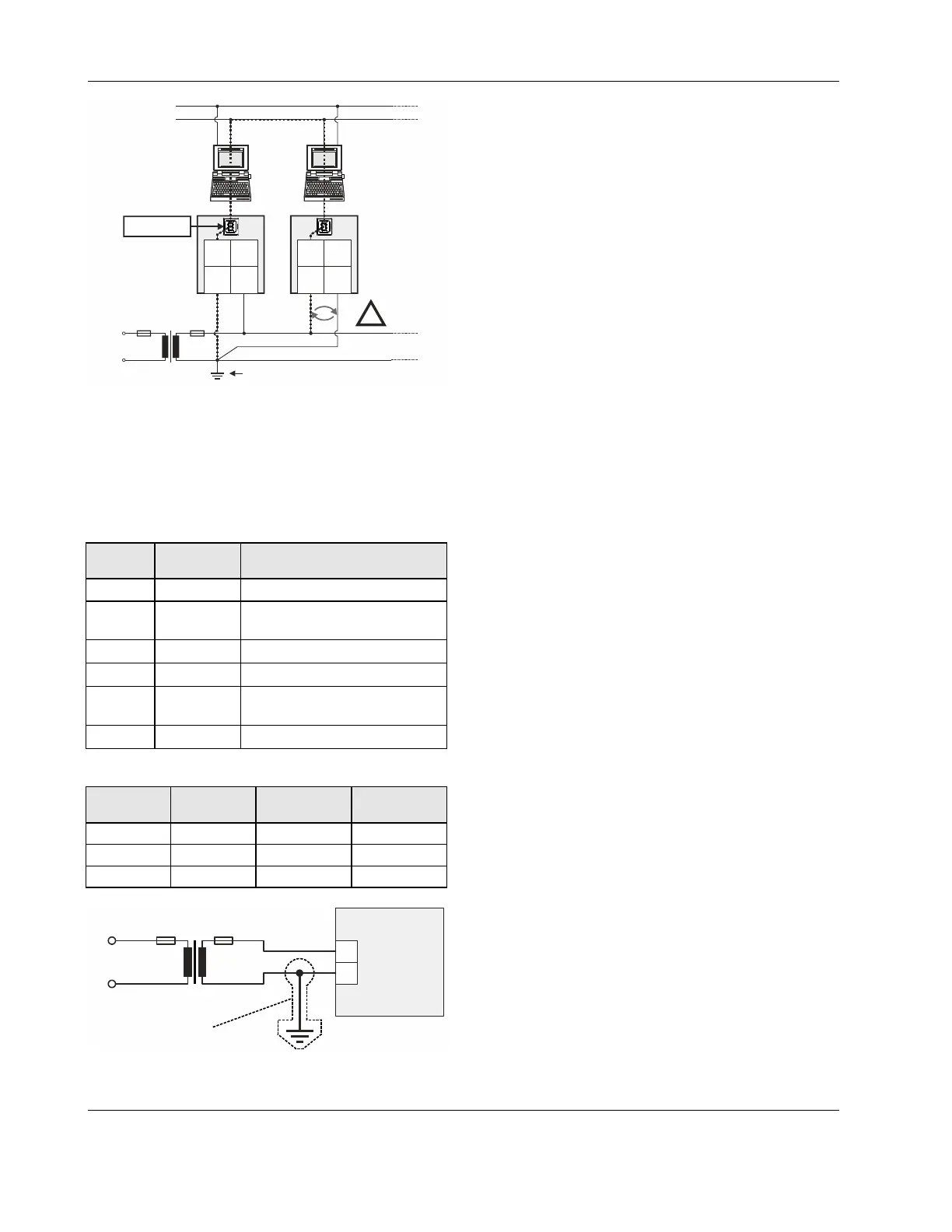
PC 1 PC 2
2 21 1
24V~ 24V~24V~0 24V~0
Fig. 15. Incorrect polarity → SHORT-CIRCUITING!
Transformer Data
In Europe, if the CLIF-CBUSLC is powered by transformers,
then such transformers must be safety isolating transformers
conforming to IEC61558-2-6. In the U.S. and Canada, if the
CLIF-CBUSLC is powered by transformers, then such trans-
formers must be NEC Class-2 transformers.
Table 10. 1450 series transformers data
part #
1450 7287
primary side secondary side
-001 120 Vac 24 Vac, 50 VA
-002 120 Vac
2 x 24 Vac, 40 VA, 100 VA from
separate transformer
-003 120 Vac 24 Vac, 100 VA, 24 Vdc, 600 mA
-004 240/220 Vac 24 Vac, 50 VA
-005 240/220 Vac
2 x 24 Vac, 40 VA, 100 VA from
separate transformer
-006 240/220 Vac 24 Vac, 100 VA, 24 Vdc, 600 mA
Table 11. Overview of CRT Series AC/DC current
transformer primary side
max. AC
current
max. DC
current
CRT 2 230 Vac 2 A 500 mA
CRT 6 230 Vac 6 A 1300 mA
CRT 12 230 Vac 12 A 2500 mA
PRIMARY SIDE
CLIF-CBUSLC
1
2
24 VAC
230 VAC
120 VAC
24 V0
NOT
RECOMMENDED
Fig. 16. Connection of CLIF-CBUSLC
RIN-APU24
The RIN-APU24 Uninterruptable Power Supply can be directly
wired to a CLIF-CBUSLC.
See RIN-APU24 Uninterruptable Power Supply – Mounting
Instructions (Product Literature no.: EN0B-0382GE51) for a
detailed wiring diagram.
Lightning Protection
Please contact your local Honeywell representative for
information on lightning protection.

 Loading...