CLIF-CBUSLC INTERFACE – INSTALLATION & COMMISSIONING INSTRUCTIONS
23 EN1Z-1026GE51 R0417
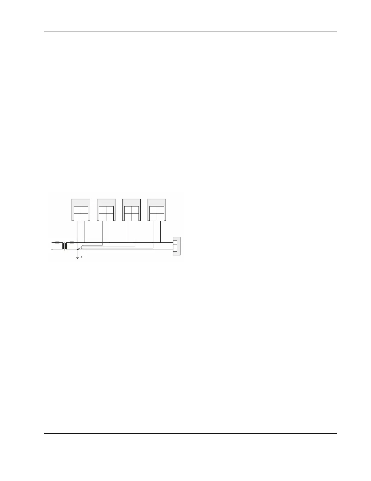
Example 2
When connecting multiple CPUs to a single transformer, it is
imperative that the polarity of the power supply terminals of
the CPUs and the polarity of the transformer always cor-
respond (namely: 24V-0 of the transformer must always be
connected to 24V-0 of the CPU, and 24V~ of the transformer
must always be connected with 24V~ of the CPU).
Depending upon the individual CPU, the numbering of the
corresponding two terminals may possibly deviate from the
norm (which is usually "terminal 1 = 24V-0" and "terminal 2 =
24V~"). In the following example, CPU 3 has a deviating
numbering and must be connected accordingly.
NOTE: When using a single transformer for several CPUs,
each CPU ground must wired separately to the
star-point.
NOTE: If the field device transformer is physically far away
from the CPUs, earth grounding must still be
performed for the controller.
NOTE: Use one star-point to split power for multiple CPUs
and field devices.
► Connect earth ground to the proper terminal of the CPU.
24 V~
24 V~0
LINE
L
N
CPU 1 CPU 2 CPU 3 CPU N
NOISE-FREE EARTH GROUND
(ONLY ONE PER SYSTEM)
2 2 2 21 1 1 1
24V~ 24V~ 24V~ 24V~24V~0 24V~0 24V~0 24V~0
GND
FIELD DEVICE
24 V~
Y
DEVIATING
NUMBERING!
Fig. 24. Connecting and earthing multiple CPUs

 Loading...