CONFIDENTIAL
Website: http://www.honeywellaircoolers.com
12
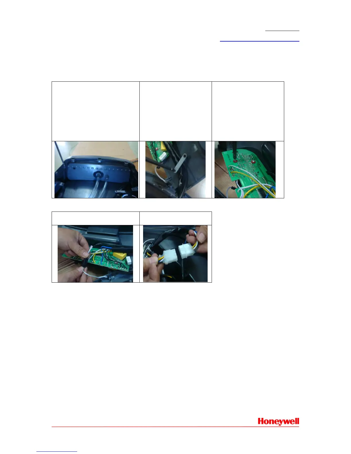
2.3 How To Change Main PCB Board
Remove the rear panel follow the procedure 2.1.1.
2.3.1. Top Panel
Use screw driver to remove 2
galvanized screw with plate
head (ST3.5*10) between the
control panel and top panel,
and then remove 2
galvanized screw with plate
head (ST3.5*10) between the
left & right panel and top
panel
Use screw driver to
remove 2 galvanized
screw with plate head
(ST3.5*10) of the wiring
pressing piece A.
Use screw driver to
remove 4 galvanized
screw with plate head
(ST3.5*10) of the PCB
board to get the PCB
board.
2.3.2 Main PCB Board Wiring Connection
Unplug the wiring
connection.
Unplug the wiring
connection.
2.3.3 Wiring Color Connection
Wiring color connection refers to part 4.2 Wiring Color Description.
 Loading...