Wiring Diagram
2
Yellow Connect to yellow of keypad
*Moose panels connect to
white of keypad
Green Connect to green of keypad
Gray (-) Channel 2 Timed Output
Red/White Channel 2 N/O relay
(Garage Door Pushbutton)
White Channel 2 Common
(Garage Door Pushbutton)
Brown Channel 3 Common
(5amp)
Brown/White Channel 3 N/O
(5amp)
Blue/Green Channel 3 N/C (5amp)
Red +12VDC
Black (-) Ground
Purple LED (-) Output
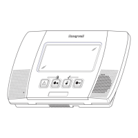
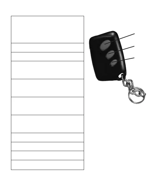
Button 1 Alarm ON/OFF/STAY**
Button 2 Garage Door OPEN/CLOSE
Button 3 PANIC OUTPUT
Hold for 3 seconds
RELAY OUTPUT
Press and Release
**Press and hold for 3 seconds to
activate “STAY” mode
Button 1
Button 2
Button 3