2 Installation Instructions Viewguard DUAL / AM FAI
1. Introduction
2. Installation Guide line
3. Installation
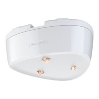
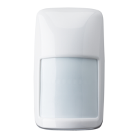
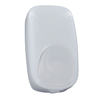
The Viewguard DUAL motion detector comprises two systems that operate fully
independently: Passive infrared detector plus Microwave detector. The functioning principle
of the detector is based on the intelligent linkage of a passive infrared sensor and
microwave. This type of linking renders the detectors particularly insensitive to air and
thermal turbulences. (Microwave module see Fig. ).
They are delivered with the following main features:
Volumetric mirror optic
, see Fig. ,
FAI (First Alarm Indication):
Selectable range and sensitivity
Memory function
Selectable range and sensitivity
Self-test
Monitoring of operating voltage
Tamper and back tamper
Maximum sensitivity is achieved when mounted crosswise to the horizontal detection
zones of the PIR sensors. Therefore, select a mounting site that runs crosswise to the
expected direction of motion. (See Fig. ).
Minimum distance to ceiling: 2 cm
* Mounting above radiators
* Mounting near air discharge openings (e.g. air conditioning systems)
* Direct sunlight
* Mounting near to fluorescent lamps
* Mounting near to light bulbs
(see Fig. 1)
If necessary, break the seal with a small screwdriver or similar object and pull downward
. Press the notch (at the bottom in the middle, see Fig. ) slightly inward and
press off the front of the housing . Lift off the housing front .
• 0° Vertical see Fig. 5/1 Fig.
• Vertical at a 3° downward angle see 5/2 Fig.
• Horizontal at a 45° angle to the left or right see 5/3 Fig.
• Corner mounting see 5/4 Fig.
The detector can be mounted by using the optional swivel bracket (see "Accessories").
(See 4)
For surface mounted wiring
For flush mounted wiring
For use with adjusting hinge
For strain relief with cable strap
3-
(see Fig. 3- , Fig. 6)
2- (only AM detectors)
Microwave sensor inactive in the "disarmed" state.
When multiple detector on a single zone, Indicate the first detector in alarm
(only AM detectors)
6-A
Due to the additional microwave, the dual detector has a very high detection capacity even
with diagonal movement. (See Fig. 6-B).
2-
4-
Fig. 4-
Fig. 4-
Fig. 4-
If the detector is not mounted at the recommended mounting height, this will have a negative
effecttothe monitored area.In this case please getin contact with our technicalsupport.
(see6.3).
Fig.
(see Fig. 4)
Required for installation according to EN 50131-2-4 grade 3.
The backtamper can be used if installed as illustrated in Fig. 5/1, 5/2, 5/3a, 5/3b and 5/4.
Tappet for backtamper. Remove the pin at the tappet, if the backtamper is
being used (see illustration)
Protective cover for back-tamper (on the rear). Remove, when mounting as
per Fig. 5/3a or 5/4
1
5
3
15
2
34
1
2
3
1
-
-
-
-
-
-
-
-
-
Avoid:
Open housing
Mounting options Screw on position
Cabling, strain relief
A
B, C
C
D
Anti-masking up to 30 cm from the detector
-
Recommended mounting height 2.5 m for optimal operating sensitivity.
Carryout a walktest for each detector inall cases
Backtamper
a
b
Installation Instructions
Viewguard Series DUAL
GB
5. Set range and sensitivity
S3 Sensitivity
ON normal
OFF high
S1 S2 Range
OFF OFF 8 m
ON OFF 11 m
OFF ON 13 m
ON ON 15 m
PIR and MW operate automatically
with the same range.
4. Connection diagram, operating modes
4.1 Terminal
Spare terminals for
end of line resistors
Fault Tamper Alarm T U F
-
+
Fault
Alarm
Tamper
Walk test
0 V
+12 V DC
arm/disarm
FAI
Fault Tamper Alarm
If the control panel has no fault input,
the "Alarm" and "Fault" outputs can
beconnected in series.
The connection of the inputs "T", "U" and "F" depending on the operating mode (see 4.2 and 4.3)
4.2 Easy Logic operating mode
Note: In this operating mode no alarm indication is available.
Microwave sensor always active.
(only AM detectors)Anti-Mask function always active
DIP-switch setting: "ON"S4, S5 and S6 in position (p 3-
)
osition see Fig.
3
Function of the walk test input "T":
open Normal operation
0 V Walk test mode (see 6.3)
Minimum of required connections: Alarm output and operating voltage (= 4 wires).
The usage of the "Walk test" input is optional. The detector is automatically in walk test mode
for10 minutes afterapplying the operating voltage (see 6.2 and6.3).
TUF
-
+
(Walk test)
0 V
+12 V DC
Unused
Unused
S4 S6 Mode ()
ON OFF Viewguard mode,
OFF OFF Viewguard mode,
ON ON Easy Logic mode, see 4.2
OFF ON
Anti-Mask only AM detectors
Anti-Mask always active
Anti-Mask inactive in "armed" state
Not allowed
Operating mode:
DIP-switch setting: (position see Fig. 3- )
3
Memory for AM function:
(only AM detectors)
S5 Mask
ON Not memory
OFF Memory
Not memory:
Memory:
(recommended operating mode)
Anti-Mask will automatically be resetted when
finishing walk test mode.
(only required for VdS applications)
Mask signal remains saved in the detector until
resetting (see below).
Reset memory: - Remove cause
- Activate walk test (inputs "T" and "U" 0 V)
- Trigger detector
- Finish walk test mode .(inputs "T" and "U" open)
FAI logic: F A I
flashes
light on
(FAI = irst larm ndication, usage optional)
The FAI connections "F" of all detectors are connected to one another. A connection to the
control panel is not required. The LED on the detector that triggers first, the LED
the subsequently triggered detectors (see 7. "LED indication").
4.3 Viewguard operating mode
Function of inputs: (Pull-up resistors in the detector)
a) armed
b) disarmed
Function
c) walk test (see 6.3),
reset alarm indication
open
0 V
Inputs
Walk test "T" Arm/disarm "U"
open
open
0 V
0 V
Walk test
0 V
+12 V DC
Arm/disarm
(FAI)
TUF
-
+
In viewguard mode, microwave part of the sensor will be deactivated when input "U" will be
connectedto 0V (paneldisarmed). See table "Operating mode"below.

 Loading...